Non-resilient Tattooing Needle and Tattooing Device

a non-resilient, tattooing needle technology, applied in the field of medical devices, can solve the problems of needle retraction speed gradually decreasing, needle cannot retract quickly, needle cannot retract at the correct speed,

Inactive Publication Date: 2017-03-16
E M MEDICAL TREATMENT & ELECTRON SUZHOU CO LTD
View PDF0 Cites 26 Cited by
  • Summary
  • Abstract
  • Description
  • Claims
  • Application Information

AI Technical Summary

Benefits of technology

[0024]The advantageous effect of the above solution is that, when connecting the sliding barrel of the barrel with the handle housing, it can be inserted into the handle housing in accordance with the long axis of the ellipse-shaped handle housing. Then, the sliding barrel is rotated in a direction from the protruding part towards the connecting area until the clamping edges are in close contact with the inner wall of the elliptical-shaped handle housing along its short axis direction. In this manner, a firm contact between the sliding barrel and the handle housing is achieved.

Problems solved by technology

First, the needle retracts by way of resilient force which requires certain deformation to work.
Thus, the retracting speed of the needle gradually decreases and certain delay will be caused so that the needle cannot retract quickly.
Second, the spring, the rubber band or the rubber ring may lose resilience after long-term use so that the needle cannot retract at the correct speed.
Third, when driving the needle, the electric motor needs to work against resilient force.
Clearly, an electric motor can be easily damaged and its service life will be shortened due to the wear and tear of the added stress put on it from the resilient force.

Method used


Image

  • Non-resilient Tattooing Needle and Tattooing Device
  • Non-resilient Tattooing Needle and Tattooing Device
  • Non-resilient Tattooing Needle and Tattooing Device

Examples


Embodiment Construction

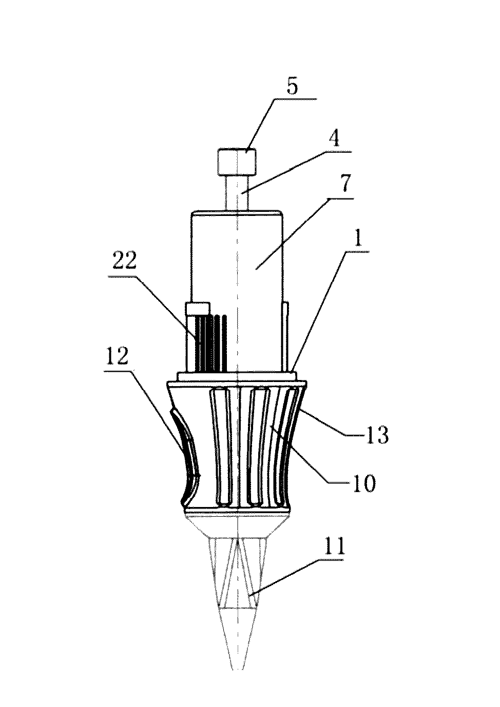
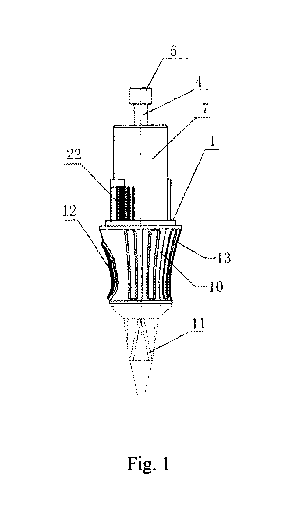
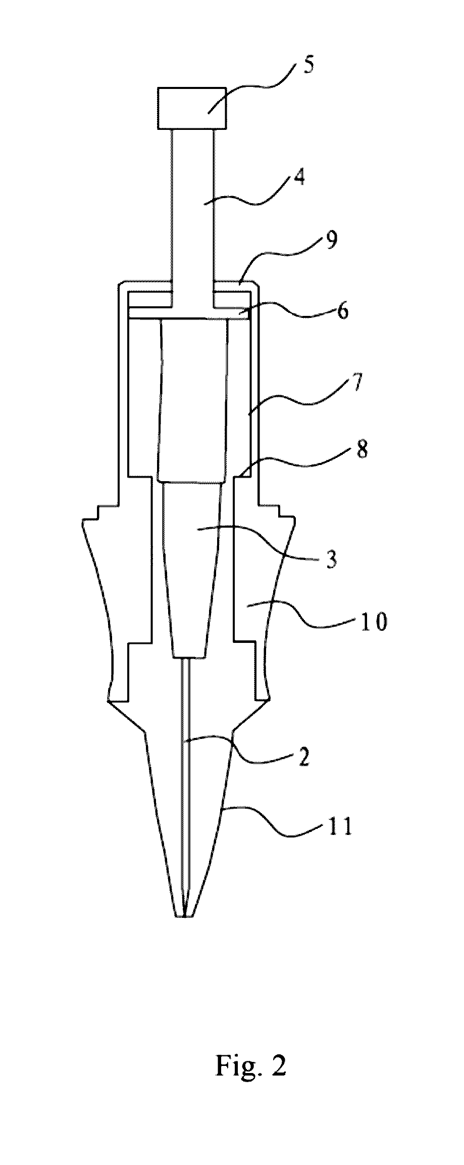
[0036]The present invention will be described in detail with reference to FIGS. 1 to 11.

[0037]FIGS. 1 to 4 are schematic drawings indicating a non-resilient tattooing needle according to an embodiment of the present invention. As shown in these figures, a non-resilient tattooing needle is provided which comprises: a barrel 1, a needle body 2 disposed inside the barrel 1, a needle base 3 for fixing / mounting the needle body 2, a first connecting rod 4 for connecting with the needle base 3 and arranged along the same axis with the needle body 2, and a first connecting part 5 disposed at the top of the first connecting rod 4.

[0038]The first connecting part 5 of the present invention reciprocates directly under an external force and thus drives the needle body 2, via the first connecting rod 4 and the needle base 3, to reciprocate linearly in the barrel 1.

[0039]The needle of the present invention does not employ any spring, rubber band or rubber ring to provide resilient force but it is ...


PUM


Abstract

The present invention discloses a non-resilient tattooing needle and a tattooing device using the same. The needle comprises a barrel, a needle body, a needle base, a first connecting rod and a first connecting part. The first connecting part of the present invention reciprocates under an external force and thus drives the needle body, via the first connecting rod and the needle base, to reciprocate linearly in the barrel. The advantageous effects of the present invention are as below: instead of using a spring, a rubber band or a rubber ring to provide a resilient force, the needle of the present invention is driven by an external force directly which enables the needle to retract quickly; such a problem is avoided that resilient forces diminish or even disappear after long-term use of the spring, the rubber band or the rubber ring which causes the needle cannot retract. The present invention also provides a tattooing device comprising an electric motor, a handle housing, a second connecting rod and an aforementioned tattooing needle. When pushing out the needle body, the electric motor does not need to work against resilient forces. Therefore, both the current and power of the electric motor are kept stable which thereby greatly prolongs the service life thereof.

Description

TECHNICAL FIELD[0001]The present invention generally relates to medical instruments and particularly to a non-resilient tattooing needle and a tattooing device.BACKGROUND[0002]In today's society, the body art industry develops increasingly fast. People would like to beautify themselves by undergoing tattooing, permanent makeup, etc. One-time usage tattooing needles and tattooing devices are all needed in these processes.[0003]Usually, a conventional tattooing device is configured such that the needle body used therein can automatically reciprocate to facilitate tattooing. A common needle employs a spring, a rubber band or a rubber ring to provide resilient force so the needle will always be forced to a retracted position. When in use, the needle body extends forward due to a driving force (such as a motor or solenoids), during which the spring, the rubber band or the rubber ring is stretched to accumulate resilient force. When the driving of the electric motor is removed, the needle...

Claims


Application Information

Patent Timeline
Patent Type & Authority Applications(United States)
IPC IPC(8): A61M37/00
CPCA61M2205/10A61M37/0076A61M37/0084A61M5/158
Inventor OSCAR, LEE BOB
Owner E M MEDICAL TREATMENT & ELECTRON SUZHOU CO LTD
Why Eureka
Try Eureka