Navier-stokes based indoor climate control

Active Publication Date: 2017-03-16
NEDERLANDSE ORG VOOR TOEGEPAST-NATUURWETENSCHAPPELIJK ONDERZOEK (TNO)
View PDF0 Cites 0 Cited by
  • Summary
  • Abstract
  • Description
  • Claims
  • Application Information

AI Technical Summary

Benefits of technology

[0062]Alternatively, predicted values may be used to even better respond to changing circumstances. I.e. according to this alternative the set of equations is jointly resolved for a plurality of time steps and based on predicted values for the vector {tilde over (Φ)} specifying the setpoint and/or the boundary conditions eΦk. In this way the system avoids an overshoot by anticipating predicte

Problems solved by technology

This phenomenon renders it difficult to provide for a homogeneous setting of climate variables as temperature, humidity, air movement, CO2 concentration in the indoor space for which the climates has to be controlled.
In a greenhouse of some hectares significant temperature and humidity differences can easily occur that lead to inconsistent quality and growth rate of the crop.
As a result of the temperature differences water vapor may locally condense and can cause mold.
Condensation of water and the resulting mold may also occur due to a local lack of air movement.
Preventing this by air-conditioning systems is power consuming.
Providing for additional ventilation, by opening windows for example, reduces the CO2 concentration and also may result in energy losses.
Current climate control systems do not adequately address these problems.
This can lead to inefficiencies, in particular if sensor-loop actuator systems are provided that control mutually different conditions, such as a temperature and a humidity.
These arrangements however do not address the dynamical interactions inside the cont

Method used


Image

  • Navier-stokes based indoor climate control
  • Navier-stokes based indoor climate control
  • Navier-stokes based indoor climate control

Examples


Embodiment Construction

[0076]Like reference symbols in the various drawings indicate like elements unless otherwise indicated.

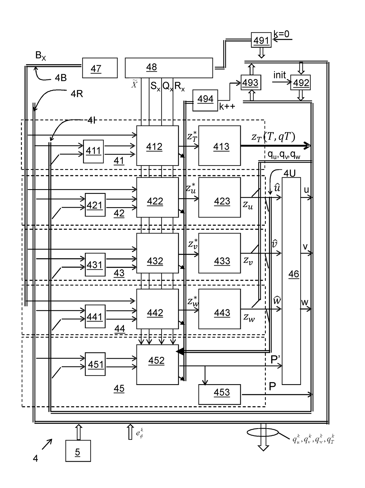
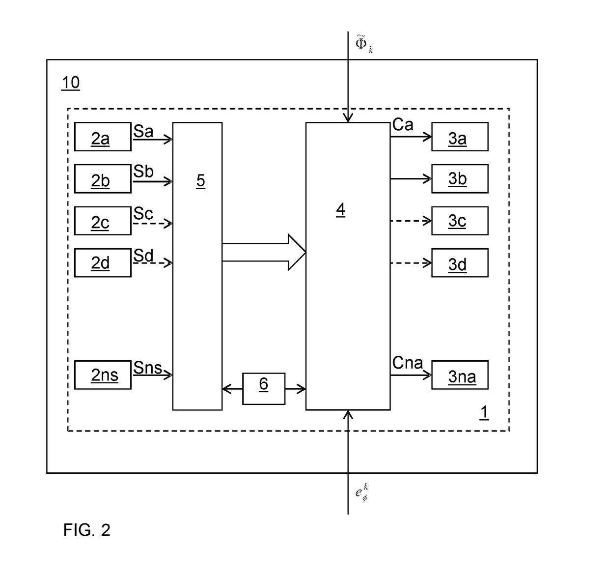
[0077]FIG. 2 schematically shows a climate control system 1 for controlling a climate in an indoor space 10. The climate control system comprises a plurality of sensors 2a, . . . 2ns to sense climate related variables in said indoor space, and to provide sensory data Sa, . . . Sn indicative for sensed values for said variables. The climate control system further comprises a plurality of actuators 3a, . . . , 3na for controlling climate related variables in said environment. A data processor 4, here serving as a controller, controls the actuators 3a, . . . , 3na on the basis of the sensory data Sa, . . . Sns. To that end the controller 4 jointly resolves a set of coupled optimization problems of the following form:

zΦk=arg min([SΦk+1 O]zΦ−{tilde over (Φ)}k+1)TQΦk([SΦk+1 O]zΦ−{tilde over (Φ)}k+1)+([O I]z101)TRΦk([O I]zΦ)  (5a)

Subject to └AΦk −BΦk┘zΦ−b′Φk(Φk,eΦk)=0  (5b)

Therein,

[0078]z...


PUM


Abstract

A data processor (4) is disclosed that can be used in a climate control system (1) for controlling a climate in an indoor space (10) or in a design system (20) for designing such a climate control system. The data processor jointly resolves a set of coupled optimization problems of the following form: Formula (5a) subject to Formula (5b) wherein: Formula (I) is an augmented state-vector comprising a vector Φ specifying the spatial distribution of a climate related variable with respect to a plurality of spatial cells, and a source term qΦ to be resolved, and wherein Formula (II) is the solution found for point in time k+1, Formula (III) being a vector specifying a setpoint specified for said climate related variable at point in time k+1 for at least a part of said plurality of cells, Formula (IV) are boundary conditions relevant for said climate related variable at point in time k, S is a selection matrix, selecting cells for said distribution having a setpoint, O is the zero matrix, I is the identity matrix and Q and R are weighting matrices for tracking and energy consumption, wherein AΦ is a matrix that defines the development of vector Φ as a function of one or more other vectors of climate related variables, wherein BΦ is a matrix that maps the source terms for field Φ to the cell field values affected by those source terms, and wherein the data processor (4) controls the plurality of said actuators in accordance with the source term qΦ.
zΦk=argmin?([SΦk1O]ZΦΦ~k1)TQΦk([SΦk1O]ZΦΦ~k1)([OI]ZΦ)TRΦk([OI]ZΦ)(5a)AΦkBΦkZΦbΦk(Φk,eΦk)=0(5b)ZΦ-[ΦqΦ](I)ZΦk-[Φk1qΦi?(II)Φ~k+1(III)eΦk?indicates text missing or illegible when filed(IV)

Description

BACKGROUND OF THE INVENTION[0001]Field of the Invention[0002]The present invention relates to a method for controlling an indoor climate.[0003]The present invention further relates to a data processor for controlling an indoor climate.[0004]The present invention further relates to system comprising such a data processor.[0005]The present invention further relates to a system for designing an indoor climate control system.[0006]The present invention further relates to a method for designing an indoor climate control system.[0007]The present invention further relates to a computer program product.[0008]Related Art[0009]An indoor climate includes various aspects that may have to be controlled, such as temperature, humidity, air movement, and CO2 concentration. An indoor climate is subject to various spatial and temporal dynamics that are in particular determined by air circulation. This phenomenon renders it difficult to provide for a homogeneous setting of climate variables as tempera...

Claims


Application Information

Patent Timeline
IPC IPC(8): F24F11/00G05D23/19G05B19/048
CPCF24F11/006G05B19/048G05B2219/2614G05D23/1928F24F2011/0061G05D23/1917F24F11/62F24F11/63F24F11/30G05B13/04G05B17/02Y02A40/25F24F11/46
Inventor BOOIJ, PAUL SEBASTIAN
Owner NEDERLANDSE ORG VOOR TOEGEPAST-NATUURWETENSCHAPPELIJK ONDERZOEK (TNO)
Why Eureka
Try Eureka