
System and Method for Facilitating the Maintenance of an Industrial Furnace

a technology for industrial furnaces and maintenance methods, applied in the direction of furnaces, programme control, instruments, etc., can solve the problems of furnace downtime and loss of production, and achieve the effect of maintaining the longevity of the furna

Inactive Publication Date: 2017-03-16
IPSEN INT
View PDF12 Cites 9 Cited by
  • Summary
  • Abstract
  • Description
  • Claims
  • Application Information

AI Technical Summary

Benefits of technology

The systems and methods of this patent provide a way to monitor equipment and determine when maintenance should be performed. This prevents failures before they occur and allows for automatic scheduling of maintenance. The invention allows for real-time monitoring and even allows for monitoring multiple furnaces with a single server. Additionally, the invention can operate even if there is no connection to the server. Overall, the invention helps to maintain the longevity of equipment and improve efficiency.

Problems solved by technology

While there are various ways to perform maintenance, there are still occasions where the furnace may break down, resulting in lost production and furnace downtime.

Method used


Image

  • System and Method for Facilitating the Maintenance of an Industrial Furnace
  • System and Method for Facilitating the Maintenance of an Industrial Furnace
  • System and Method for Facilitating the Maintenance of an Industrial Furnace

Examples


Embodiment Construction

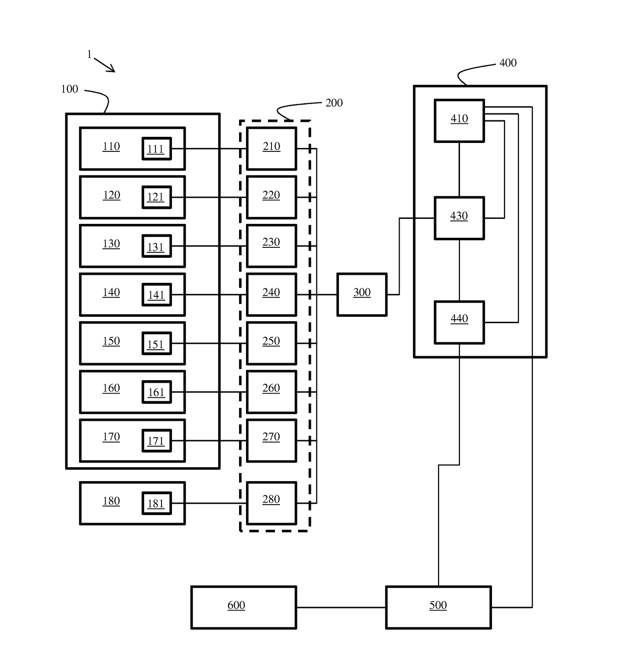
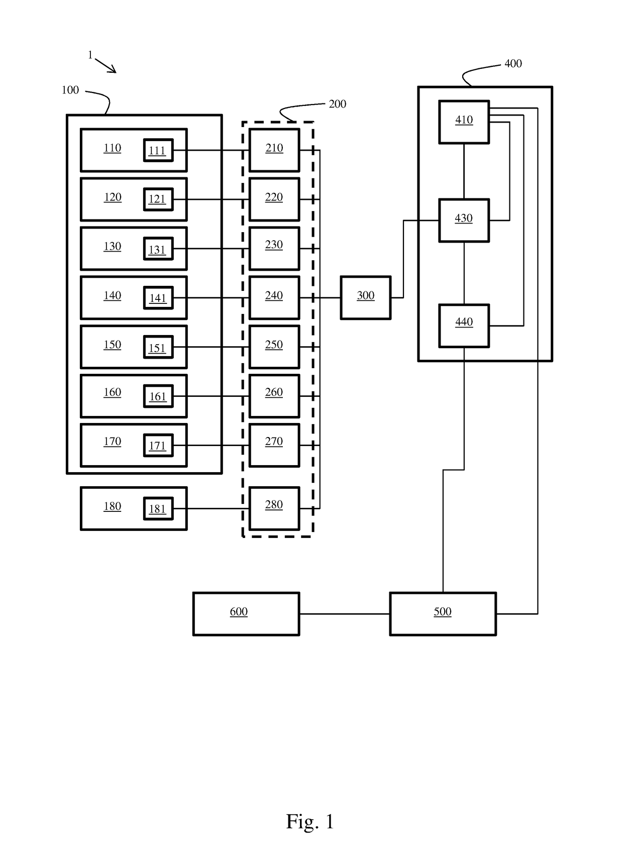
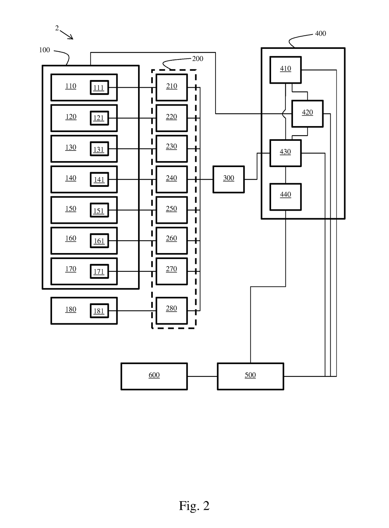
[0028]Referring now to the figures, wherein like elements are numbered alike throughout, FIG. 1 provides an exemplary system 1 for maintaining or otherwise aiding in the maintenance of an industrial heat treating furnace 100.

[0029]Industrial heat treating furnaces are generally defined as either (1) positive pressure or atmospheric furnaces which operate at about standard atmospheric pressure; or (2) vacuum furnaces, which heat a material under a vacuum. Certain heat treatment processes dictate the use of a vacuum during some period of a heating cycle. As used herein, “vacuum furnace” means a furnace that applies a vacuum in the furnace chamber during any portion of a heat treating cycle. For example, if a vacuum is used only to purge the furnace chamber prior to performing a heating and cooling heat treating process at positive pressure, the furnace is a vacuum furnace. In certain preferred aspects, the furnace 100 is a vacuum furnace.

[0030]Various exemplary furnaces are known in t...


PUM


Abstract

A system and method for facilitating the maintenance of an industrial heat treating furnace are disclosed.

Description

CROSS REFERENCE TO RELATED APPLICATIONS[0001]This application claims the benefit of U.S. provisional patent application No. 62 / 217,230, filed Sep. 11, 2015, the entirety of which is incorporated herein by reference.FIELD OF THE INVENTION[0002]The present invention relates generally to a system and method for facilitating the maintenance of an industrial heat treating furnace and more particularly, but not exclusively, to a system and method for automatically determining whether an industrial furnace requires or will require maintenance due to a failure condition in one or more furnace components.BACKGROUND OF THE INVENTION[0003]In the world of heat treatment, furnaces must often withstand extreme conditions. However, for consistent, high-quality results, the furnace should be kept in excellent condition. While there are various ways to perform maintenance, there are still occasions where the furnace may break down, resulting in lost production and furnace downtime.[0004]Accordingly,...

Claims


Application Information

Patent Timeline
Patent Type & Authority Applications(United States)
IPC IPC(8): F27D21/00F27D19/00F27D21/04G05B23/02
CPCF27D21/00G05B23/024F27D19/00F27D2021/0057G05B2219/24019F27D21/0021F27D21/04C21D11/00
Inventor SOMARY, GEOFFREYMOLLER, CRAIGGRANN, JIMGOLDSTEINAS, AYMERIC
Owner IPSEN INT
Learn More