In-vehicle equipment

a technology for in-vehicle equipment and equipment, which is applied in the direction of process control, safety/protection circuit, instruments, etc., can solve the problems of increasing cost, increasing device size, and unable to avoid the increase in cost, so as to reduce the size and cost of in-vehicle equipment

Active Publication Date: 2017-03-16
MITSUBISHI ELECTRIC CORP
View PDF2 Cites 3 Cited by
  • Summary
  • Abstract
  • Description
  • Claims
  • Application Information

AI Technical Summary

Benefits of technology

[0015]According to the present invention, since it is configured that the drive voltage to turn on the FET of the power supply reverse connection protector is generated by using the voltage generated in the step-down DC / DC converter, it is possible to achieve reductions in size and cost of the in-vehicle equipment as compared with a case where a charge pump-type booster circuit is used.

Problems solved by technology

Since the charge pump-type booster circuit requires many components such as a capacitor for boosting switching, a capacitor for smoothing, a plurality of switching elements for controlling charging and discharging of the capacitor for boosting switching, and a control circuit for switching between ON and OFF of the switching elements, the booster circuit becomes a factor responsible for an increase in size of a device and an increase in cost.
However, these devices serve as means for avoiding the increase in size of the device, but the increase in cost cannot be avoided.

Method used


Image

  • In-vehicle equipment
  • In-vehicle equipment
  • In-vehicle equipment

Examples


embodiment 1

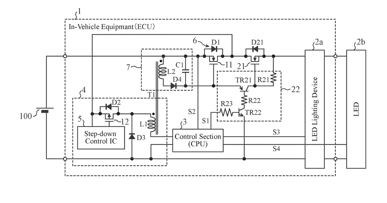
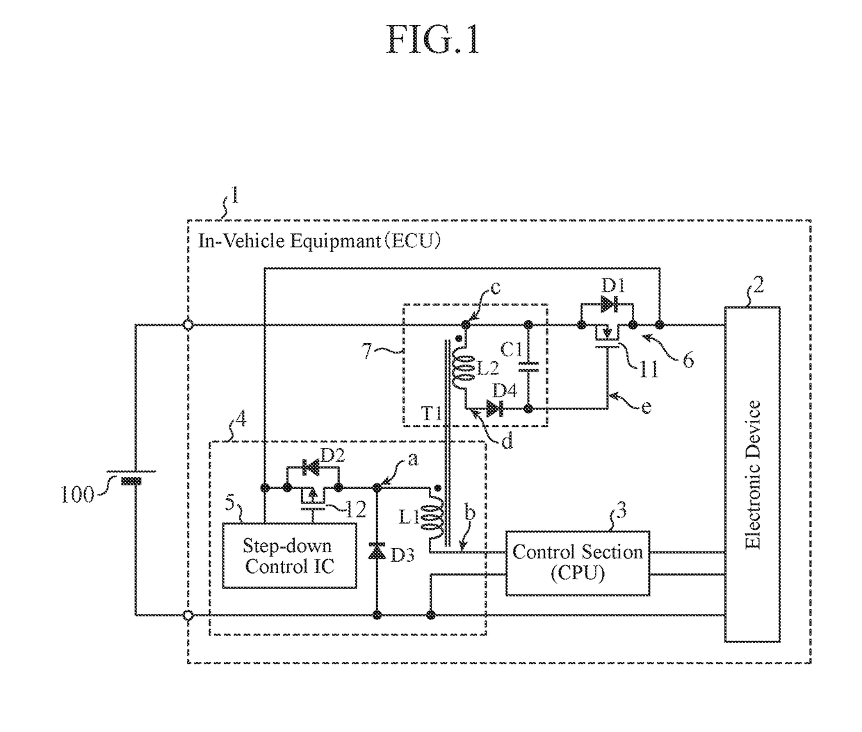
[0026]As shown in FIG. 1, in-vehicle equipment 1 according to Embodiment 1 includes: an electronic device 2 that operates using an in-vehicle battery 100 as a power supply; a control section 3 that controls the electronic device 2; a first power supply section 4 of a step-down DC / DC converter (buck converter, step-down converter etc.) type that supplies power to the control section 3; a power supply reverse connection protection section 6 that prevents a reverse current that flows in a case where the battery 100 and the electronic device 2 are connected with a reverse polarity; and a second power supply section 7 that generates a drive voltage to drive the power supply reverse connection protection section 6.

[0027]In the following, a case where the battery 100 is connected to the in-vehicle equipment 1 with a positive polarity is referred to as normal connection, and a case where the battery 100 is connected to the in-vehicle equipment 1 with the reverse polarity is referred to as r...

embodiment 2

[0057]FIG. 3 is a circuit diagram showing a configuration of in-vehicle equipment 1 according to Embodiment 2. Parts in FIG. 3 identical or equivalent to those in FIG. 1 are denoted by the same reference numerals, and descriptions thereof will be omitted.

[0058]In Embodiment 2, an N-channel FET 11a of the power supply reverse connection protection section 6 is arranged on the minus terminal side of the battery 100.

[0059]In the case where the N-channel FET 11 is connected to the plus terminal side of the battery 100 (FIG. 1), the anode terminal of the parasitic diode D1 is connected to the battery 100 and the cathode terminal thereof is connected to the electronic device 2, while in the case where the N-channel FET 11a is connected to the minus terminal side (FIG. 3), the anode terminal of the parasitic diode D1 is connected to the electronic device 2, and the cathode terminal thereof is connected to the minus terminal of the battery 100. In addition, the winding end portion of the pr...

embodiment 3

[0061]FIG. 4 is a circuit diagram showing a configuration of in-vehicle equipment 1 according to Embodiment 3. Parts in FIG. 4 identical or equivalent to those in FIG. 1 are denoted by the same reference numerals, and descriptions thereof will be omitted.

[0062]In Embodiment 3, a P-channel FET 11b is used as the semiconductor switch of the power supply reverse connection protection section 6.

[0063]In the case where the N-channel FET 11 is used (FIG. 1), the winding start portion of the secondary winding L2 of the transformer T1 is connected to the battery 100 and the winding end portion of the secondary winding L2 is connected to the rectifier diode D4, while in a case where the P-channel FET 11b is used (FIG. 4), the winding direction of the secondary winding L2 of the transformer T1 is reversed, the winding end portion of the secondary winding L2 is connected to the battery 100, and the winding start portion of the secondary winding L2 is connected to the rectifier diode D4. In add...


PUM


Abstract

A FET of a power supply reverse connection protection section is connected between a battery and an electronic device, and at a time of reverse connection of the battery, the FET is turned off and a parasitic diode of the FET prevents a current flowing in a direction opposite to a direction at a time of normal connection. A transformer is used in a DC / DC converter of a first power supply section that supplies power to a control section, and a voltage generated in a secondary winding is applied to the FET.

Description

TECHNICAL FIELD[0001]The invention relates to in-vehicle equipment having a function of preventing, at reverse connection of a battery, a current from flowing in a direction opposite to that at normal connection thereof.BACKGROUND ART[0002]A power supply reverse connection protection function that prevents, in a case where a plus terminal and a minus terminal of an in-vehicle battery are connected reversely, a failure of in-vehicle equipment due to a current flow in a direction opposite to that in a normally connected case is proposed in, e.g., each of Patent Documents 1 and 2.[0003]In a power supply reverse connection protection circuit according to Patent Document 1, on a power supply wiring that connects a power supply terminal connected to a plus terminal of a battery and a control circuit as a power supply target, an N-channel first FET (field-effect transistor) is provided such that an anode of a parasitic diode of the first FET is situated at the side of the power supply term...

Claims


Application Information

Patent Timeline
Patent Type & Authority Applications(United States)
IPC IPC(8): H05B33/08B60R16/033H02J7/00H02M3/156H02M1/08H05B44/00
CPCH02M1/32H05B33/089H02M3/156H02J2007/0067H02J7/0029H02J7/0065B60R16/033H02M1/08G01R19/14H02J7/0034H02H11/003H02J2310/40Y02B20/30H02H11/002H02H11/00H02J2207/20
Inventor OKITA, SHUICHI
Owner MITSUBISHI ELECTRIC CORP
Why Eureka
Try Eureka