
System and Methods for Automated Plant Asset Failure Detection

a plant asset and system technology, applied in the field of system and method for automated plant asset failure detection, can solve the problems of high cost of production, high labor intensity, and high labor intensity of large manufacturers, and achieve the effects of reducing labor intensity, reducing labor intensity, and increasing energy costs

Active Publication Date: 2017-03-23
ASPENTECH CORP
View PDF0 Cites 7 Cited by
  • Summary
  • Abstract
  • Description
  • Claims
  • Application Information

AI Technical Summary

Benefits of technology

The present patent is about a system and method for recognizing failures in equipment by analyzing sensor data and identifying patterns that indicate impending failure. The system can also detect abnormal conditions in equipment and train an agent to alert when a failure occurs. The system can be used for failure signature recognition training, equipment monitoring, and anomaly detection. The technical effects of the patent include improving equipment reliability, preventing failures, and identifying potential threats to equipment safety.

Problems solved by technology

Large manufacturers today face extreme margin pressures from low-cost producers, rising energy costs, and regulatory and environmental restrictions.
One barrier to improvement has been the absence of a performance management solution encompassing the various divisions of operations, maintenance, and finance, for example.
With each division using its own performance metrics, it is difficult for optimal decisions to be made, such as balancing reliability goals against asset utilization goals.
However, one of the greatest challenges for effectively improving plant asset performance is that the necessary information is scattered across disconnected silos of data in each department.
Furthermore, it is difficult to integrate these silos due to several fundamental differences.
Furthermore, different vendors of various equipment and enterprise systems tend to have their own set of codes (e.g., status codes) and are non compliant with any universal standard.
Manufacturers are drowning in a flood of real-time and non-real time data and are losing revenues at the same time.

Method used


Image

  • System and Methods for Automated Plant Asset Failure Detection
  • System and Methods for Automated Plant Asset Failure Detection
  • System and Methods for Automated Plant Asset Failure Detection

Examples


Embodiment Construction

[0030]A description of example embodiments of the invention follows.

[0031]The teachings of all patents, published applications and references cited herein are incorporated by reference in their entirety.

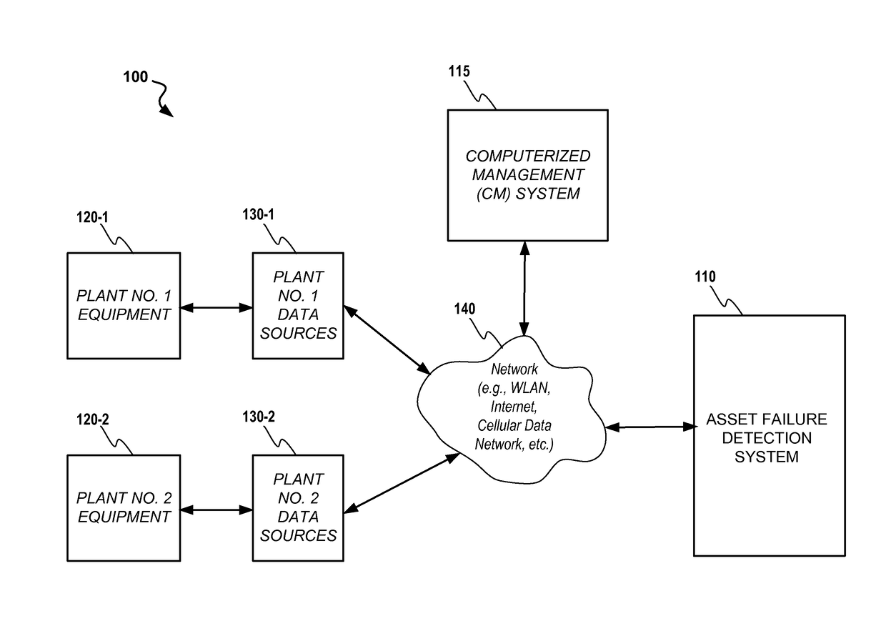
[0032]Referring now to the drawings, where like or similar elements are designated with identical reference numerals throughout the several views, and referring in particular to FIG. 1, it illustrates a block diagram of an exemplary system 100 for performing asset failure detection in accordance with the disclosure. The system 100 includes an asset failure detection system 110, a computerized management (CM) system (also known as a computerized maintenance management system or CMMS), a first plant 120-1 with equipment coupled to first plant data sources 130-1, a second plant 120-2 with equipment coupled to second plant data sources 130-2 and a communication network (e.g., the Internet, a WLAN, a cellular data network or other communication network) communicatively coupling the other ...


PUM


Abstract

A system for performing failure signature recognition training for at least one unit of equipment. The system includes a memory and a processor coupled to the memory. The processor is configured by computer code to receive sensor data relating to the unit of equipment and to receive failure information relating to equipment failures. The processor is further configured to analyze the sensor data in view of the failure information in order to develop at least one learning agent for performing failure signature recognition with respect to the at least one unit of equipment.

Description

RELATED APPLICATIONS[0001]This application is a continuation of U.S. application Ser. No. 14 / 217,265, filed Mar. 17, 2014, which claims the benefit of U.S. Provisional Application No. 61 / 802,293 entitled “System And Methods For Automated Plant Asset Failure Detection”, filed on Mar. 15, 2013, the disclosure of which is incorporated herein by reference in its entirety for all purposes. The present application is related to commonly owned and assigned U.S. application Ser. No. 11 / 740,404 (now U.S. Pat. No. 8,380,842), entitled “System and Methods for the Universal Integration of Plant Floor Assets and a Computerized Management System”, filed Apr. 26, 2007, and is now issued as U.S. Pat. No. 8,380,842 on Feb. 19, 2013. The entire teachings of the above applications are incorporated herein by reference.FIELD[0002]The systems and methods disclosed herein relate to preventing failure in industrial equipment and other plant assets.BACKGROUND[0003]Large manufacturers today face extreme marg...

Claims


Application Information

Patent Timeline
IPC IPC(8): G06N99/00G06N20/00
CPCG06N99/005G05B23/0229G06N20/00G06F21/552G05B23/024G06F11/0709G06F11/2257
Inventor BATES, ALEXANDER B.RAHILLY, PAULMACNAB, SCOTT
Owner ASPENTECH CORP
Learn More