
Electrical receptacle connector

Active Publication Date: 2017-03-23
ADVANCED CONNECTEK INC
View PDF3 Cites 2 Cited by
  • Summary
  • Abstract
  • Description
  • Claims
  • Application Information

AI Technical Summary

Benefits of technology

The patent describes a way to create a flexible adapter that allows different types of connectors to be used with a standard piece of hardware. This is particularly useful in applications where different types of connectors are needed for different parts of a system. The design allows for easy repairs and standardized pin assignments, making it easier to maintain and modify the hardware. Overall, this design simplifies the process of integrating different components into a single system.

Problems solved by technology

During high frequency signal transmission, severe crosstalk between terminals may occur in the case of the common USB 2.0 interfaces.
In addition, the conventional USB 2.0 interfaces may suffer from radiofrequency interference (RFI) as well as electromagnetic interference (EMI) easily.
Regarding to the USB 3.0 interfaces, the crosstalk and interference problems may become serious due to the higher transmission speed which can be more than 5 Gbs of the USB 3.0 interfaces.
Nevertheless, the metallic shell commonly has a rear cover, which may increase the difficulty for soldering tail portions of the terminals on the circuit board during a packaging procedure.
Therefore, upon the soldering procedure, solder empty or non-wetting problems may occur.
Due that the structures of the components become complex and due to the aforementioned structure of the metallic shell, a person cannot check if holes or grooves of the circuit board are properly mated with the terminals (i.e., whether or not the pin assignments between the circuit board and the terminals are in right positions), and the connector may be difficult to be repaired.
As a result, once the connector is damaged, the whole receptacle has to be detached from the assembled circuit board and repaired separately.
Therefore, the overall cost for repairing the connector assembly may be very expensive.

Method used


Image

  • Electrical receptacle connector
  • Electrical receptacle connector
  • Electrical receptacle connector

Examples


Embodiment Construction

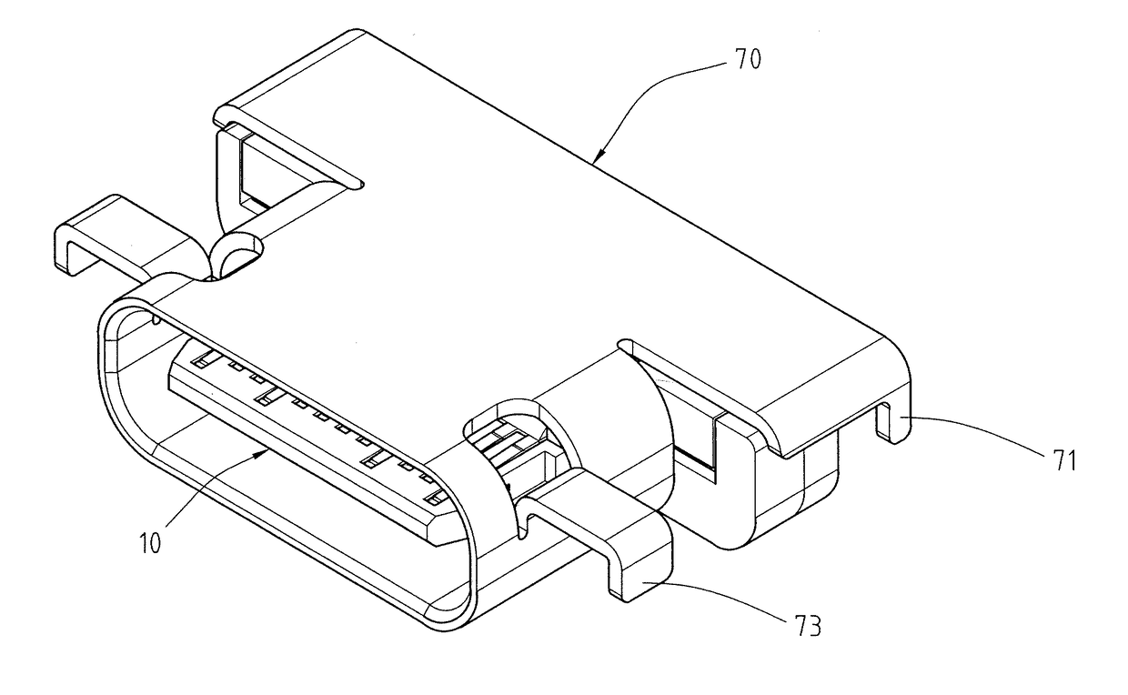
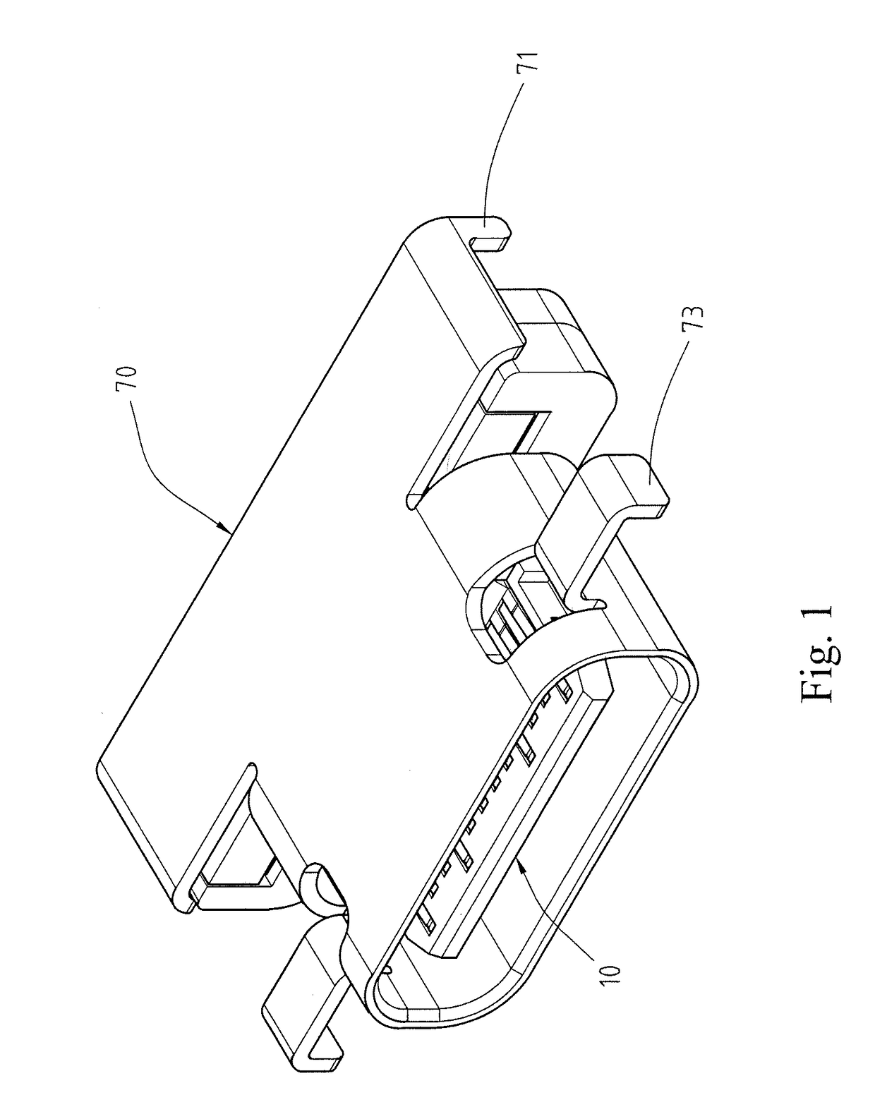
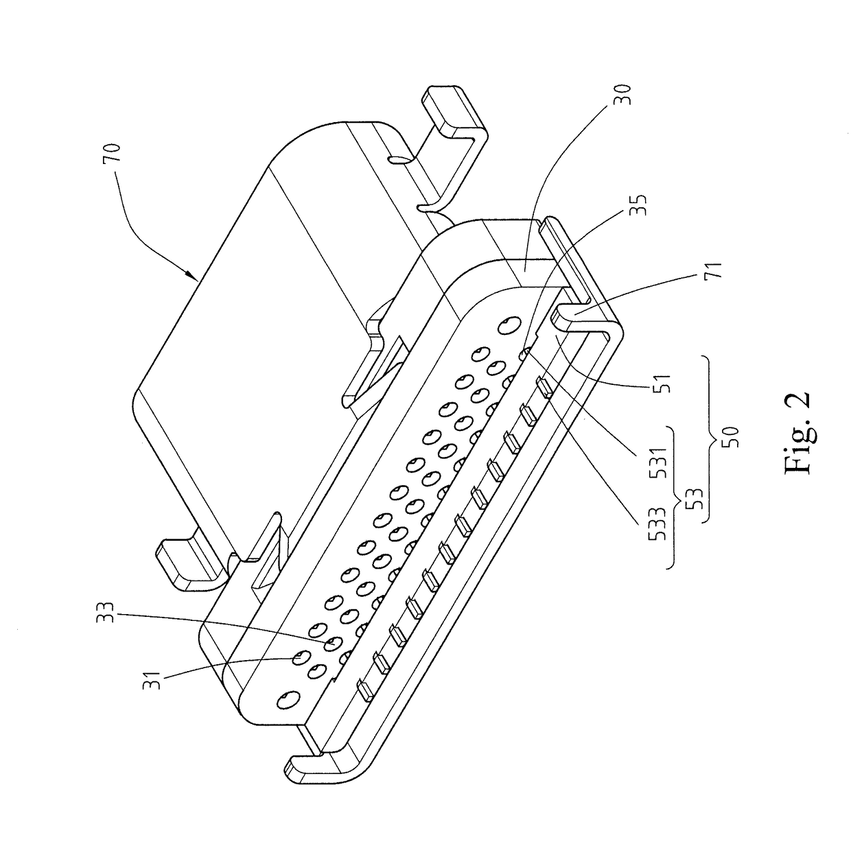
[0026]Please refer to FIGS. 1 to 4, illustrating an electrical receptacle connector of an exemplary embodiment of the instant disclosure. FIG. 1 illustrates a perspective view of an electrical receptacle connector according to an exemplary embodiment of the instant disclosure. FIG. 2 illustrates a perspective view from the rear of the electrical receptacle connector of FIG. 1. FIG. 3 illustrates a partial exploded view of the electrical receptacle connector of FIG. 1. FIG. 4 illustrates a partial plan sectional view of an adapting circuit board and an adapting terminal module of the electrical receptacle connector of FIG. 1. As shown in FIGS. 1 to 4, the electrical receptacle connector 1 comprises an insertion module 10, an adapting circuit board 30, and an adapting terminal module 50.

[0027]As shown in FIGS. 2 and 3, the insertion module 10 and the adapting terminal module 50 are respectively on a first side 30A and a second side 30B of the adapting circuit board 30. The insertion m...


PUM


Abstract

An electrical receptacle connector includes an insertion module, an adapting circuit board, and an adapting terminal module. The insertion module and the adapting terminal module are on the adapting circuit board. The insertion module includes first and second receptacle terminals, a grounding plate, and an insulated housing. The first and the second receptacle terminals are fixed on the insulated housing. First and second tail portions of the first and the second receptacle terminals are protruding from the insulated housing, respectively. The adapting circuit board includes first, second, and third soldering portions. The first, second, and third tail portions are soldered with the first, second, and third soldering portions, respectively. The third receptacle terminal includes a third tail portion and a fourth tail portion. The third tail portions are soldered with the third soldering portions, and the fourth tail portions are protruding from the adapting insulated member.

Description

CROSS-REFERENCE TO RELATED APPLICATION[0001]This non-provisional application claims priority under 35 U.S.C. §119(a) to Patent Application No. 201510607495.9 filed in China, P.R.C. on Sep. 23, 2015, the entire contents of which are hereby incorporated by reference.FIELD OF THE INVENTION[0002]The instant disclosure relates to an electrical connector, and more particular to an electrical receptacle connector.BACKGROUND[0003]Universal Serial Bus (USB) is a serial bus standard commonly applied for computer, communication, and consumer electronics. Due to the developments of products in different aspects, demands for higher transmission speeds are urging. During high frequency signal transmission, severe crosstalk between terminals may occur in the case of the common USB 2.0 interfaces. In addition, the conventional USB 2.0 interfaces may suffer from radiofrequency interference (RFI) as well as electromagnetic interference (EMI) easily.[0004]Regarding to the USB 3.0 interfaces, the cross...

Claims


Application Information

Patent Timeline
IPC IPC(8): H01R12/70H01R24/60
CPCH01R12/7082H01R2107/00H01R24/60H01R12/722H01R13/6594
Inventor CHEN, CHING-TIENDUAN, SHU-LINWAN, WEIQI, XIAO-JUAN
Owner ADVANCED CONNECTEK INC
Features
  • Generate Ideas
  • Intellectual Property
  • Life Sciences
  • Materials
  • Tech Scout
  • Unparalleled Data Quality
  • Higher Quality Content
  • 60% Fewer Hallucinations
Learn More