Method and Device for Implementing Laser Shock Peening or Warm Laser Shock Peening During Selective Laser Melting

a laser melting and laser technology, applied in the field of methods and devices, can solve the problems of limited parts built by slm technology, inadequate mechanical properties compared to conventionally produced parts, increased surface roughness, etc., and achieves the effects of increasing the depth of shockwave penetration, increasing the shock wave pressure, and rapid expansion

Active Publication Date: 2017-03-30
ECOLE POLYTECHNIQUE FEDERALE DE LAUSANNE (EPFL)
View PDF24 Cites 35 Cited by
  • Summary
  • Abstract
  • Description
  • Claims
  • Application Information

AI Technical Summary

Problems solved by technology

Some of the biggest limitations of parts built by the SLM technology are their inadequate mechanical properties compared to conventionally produced parts.
These limitations are well studied and are the result of unfavorable tensile residual stresses (TRS), increased surface roughness, and lower part density.
This results in a need for subsequent thermal / mechanical treatment which is limiting the SLM process application.

Method used


Image

  • Method and Device for Implementing Laser Shock Peening or Warm Laser Shock Peening During Selective Laser Melting
  • Method and Device for Implementing Laser Shock Peening or Warm Laser Shock Peening During Selective Laser Melting
  • Method and Device for Implementing Laser Shock Peening or Warm Laser Shock Peening During Selective Laser Melting

Examples


Embodiment Construction

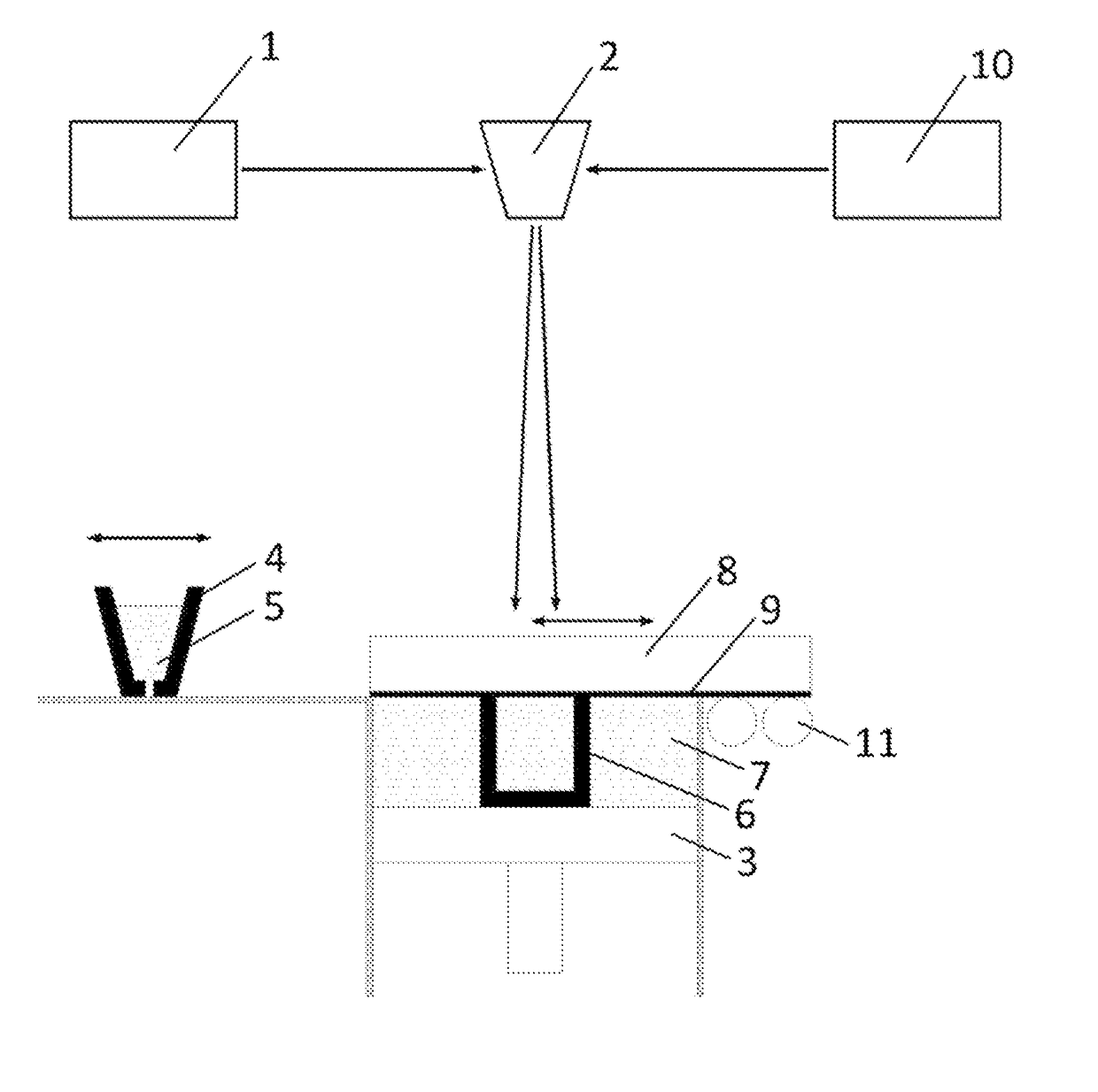
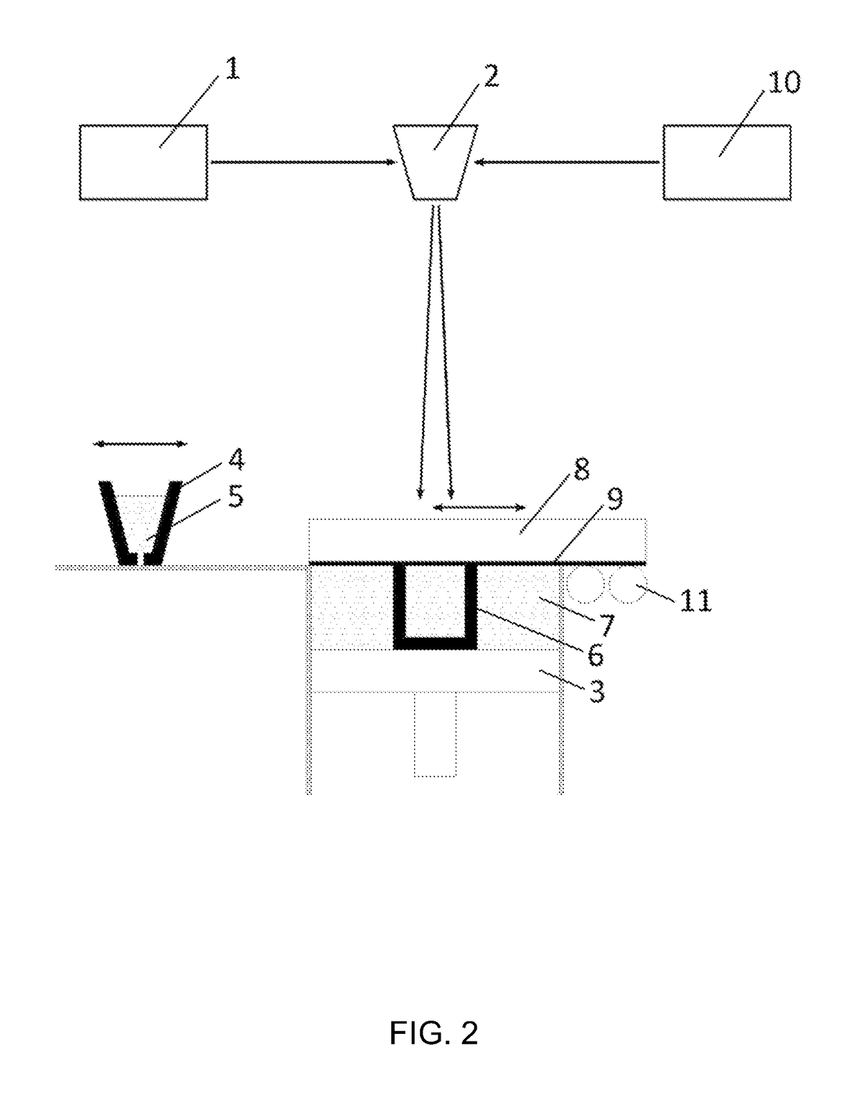
[0031]A first idea of the present invention is to provide a device and a method for introducing Laser shock Peening (LSP) or Warm Laser Shock Peening (WLSP) during Selective Laser Melting (SLM) in order to change the residual stress field from a detrimental tensile residual stress (TRS) which is inherited from the SLM process, to a beneficial compressive residual stress (CRS) field in chosen critical zones, for example in the near surface region. This is resulting in improved mechanical properties and fatigue life of the part or article 6 (in situ) directly while it is being built and eliminates or at least reduces the need for post processing.

[0032]This approach leads to improvements of mechanical properties of the finished part 6 in much larger depths than with conventional post processing techniques. This effect is due to the use of LSP or WLSP throughout the volume of the part 6 while it is being built, instead of just as a surface treatment of a finished part 6. With such an ap...


PUM

PropertyMeasurementUnit
temperatureaaaaaaaaaa
temperaturesaaaaaaaaaa
residual stressaaaaaaaaaa

Abstract

A method for manufacturing an object including the steps of forming layers by adding successive layers of material to form the object by selective laser melting (SLM), and inducing plastic deformation and residual stress into solidified material of at least one of the successive layers of material to improve mechanical properties and a fatigue resistance of the object, wherein the plastic deformation and the residual stress are induced by a laser.

Description

CROSS-REFERENCE TO RELATED APPLICATIONS[0001]The present application claims foreign priority to earlier European patent application Nos. EP15187188.6 filed on Sep. 28, 2015 and EP 16162065.3 filed on Mar. 23, 2016, the content of these earlier applications being incorporated by reference in their entirety in the present application.BACKGROUND ART[0002]Selective Laser Melting (SLM, shown in FIG. 1), also known as Direct Metal Laser Sintering (DMLS), Laser Cusing or Selective Laser Sintering (SLS) is an Additive Manufacturing process in which parts are built layer by layer out of a metallic, ceramic or polymer powder.[0003]FIG. 1 illustrates a standard SLM process of the background art. At each step of the process, a powder bed is deposited on a substrate and selectively melted by a laser beam 1 piloted by a CAM system through a scanning head 2. After solidification, the material gets consolidated, a building platform 3 is lowered for the value of the wanted layer height and a new pow...

Claims


Application Information

Patent Timeline
Patent Type & Authority Applications(United States)
IPC IPC(8): B23K26/342B33Y10/00B23K26/356B33Y40/00B23K26/00C21D10/00B33Y30/00
CPCB23K26/342C21D10/005B33Y10/00B23K26/356B33Y40/00B23K26/0069B23K26/009B33Y30/00C21D7/06C21D1/38B29C64/153B29C64/188Y02P10/25B22F12/44B22F10/28B22F12/43B22F12/10B22F10/50B22F10/38B22F12/45
Inventor KALENTICS, NIKOLALOGE, ROLANDBOILLAT, ERIC
Owner ECOLE POLYTECHNIQUE FEDERALE DE LAUSANNE (EPFL)
Why Eureka
Try Eureka