Turbine blade squealer tip

Inactive Publication Date: 2012-02-09
SIEMENS ENERGY INC
View PDF9 Cites 39 Cited by
  • Summary
  • Abstract
  • Description
  • Claims
  • Application Information

AI Technical Summary

Benefits of technology

[0005]A turbine blade having a squealer tip coupled to a radially outer end of the turbine blade that is usable in a gas turbine engine is disclosed. The squealer tip may be configured such that the squealer tip requires less cooling fluids than conventional squealer tips, therefore increasing the efficiency of the turbine engine in which the squealer tip is used. In at least one embodim

Problems solved by technology

In addition, turbine blades often contain cooling systems for prolonging the life of the blades and reducing the likelihood of failure as a result of excessive temperatures.
These higher temperatures are creating increased thermal stress levels on the turbine airfoils.
However, centrifugal forces and air flow at bounda

Method used


Image

  • Turbine blade squealer tip
  • Turbine blade squealer tip
  • Turbine blade squealer tip

Examples


Embodiment Construction

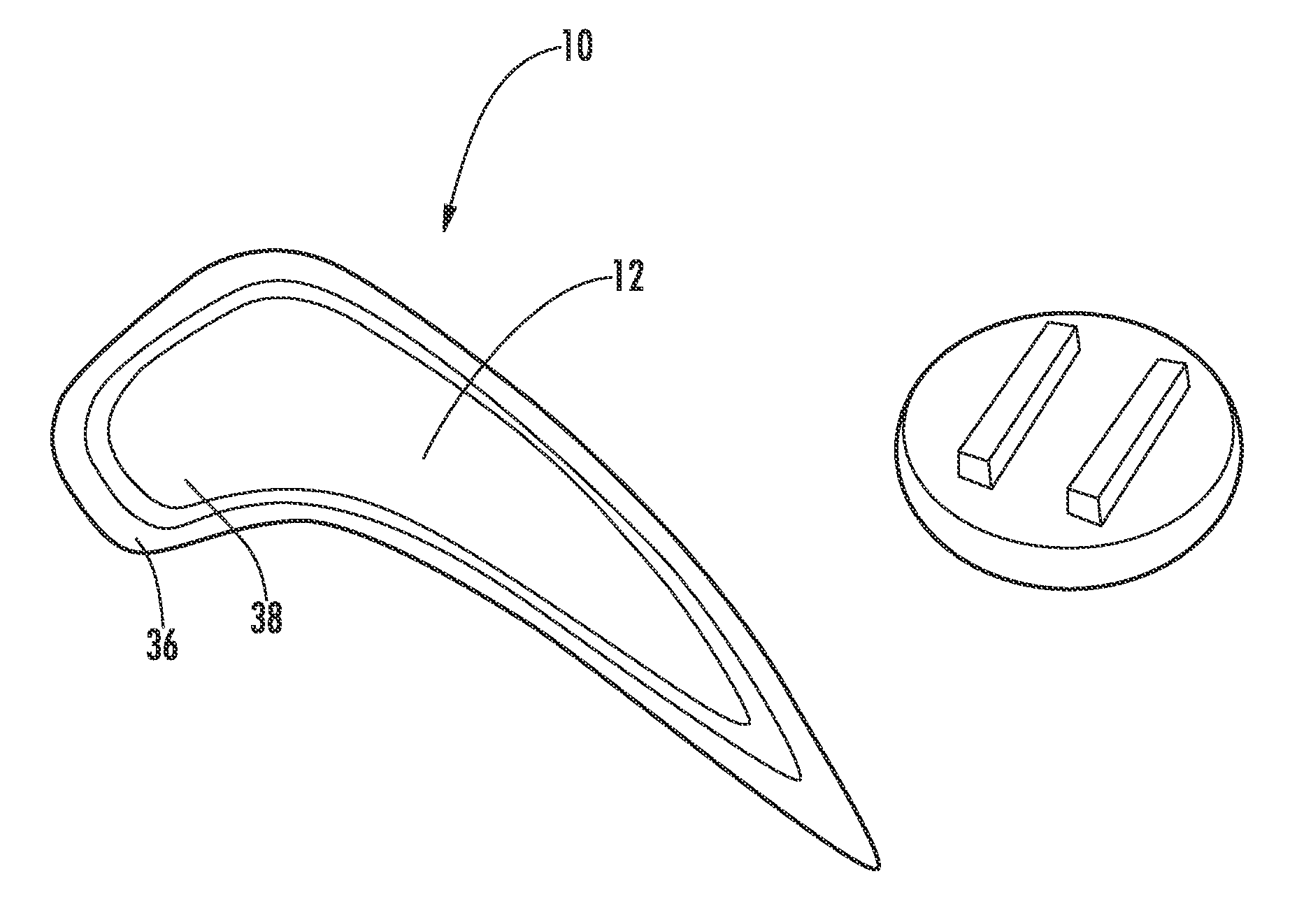
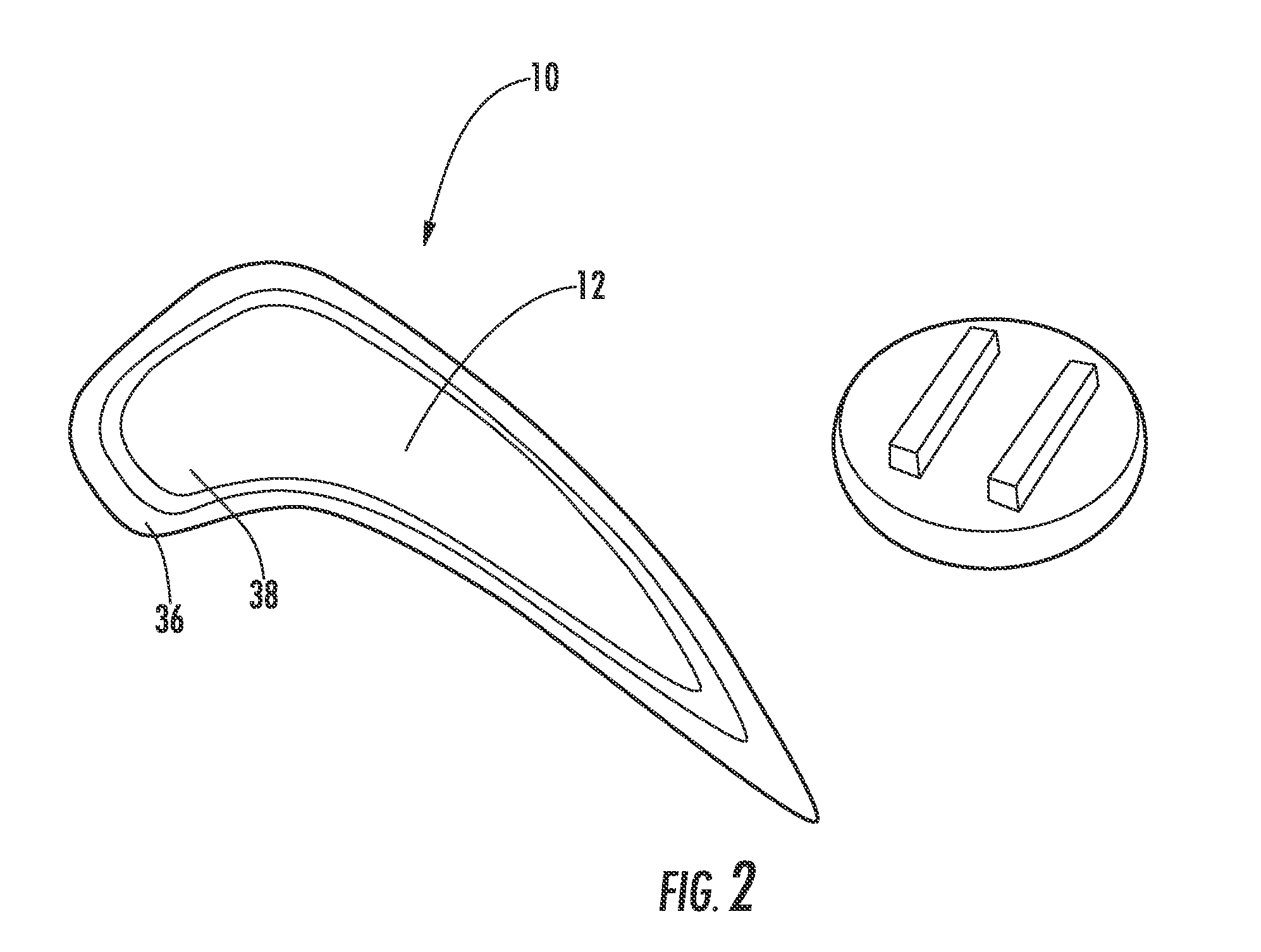
[0019]As shown in FIGS. 1-5, this invention is directed to a turbine blade 10 having a squealer tip 12 for use in turbine engines. The squealer tip 12 may be configured such that the squealer tip 12 requires less cooling fluids than conventional squealer tips, thereby increasing the efficiency of the turbine engine in which the squealer tip 12 is used. In at least one embodiment, the squealer tip 12 may use about 1.5 percent less cooling fluids than conventional turbine blades. In addition, the squealer tip 12 may also be configured to be used in turbine engines that are designed to operate at higher operating temperatures than conventional turbine engines without an increased risk of failure.

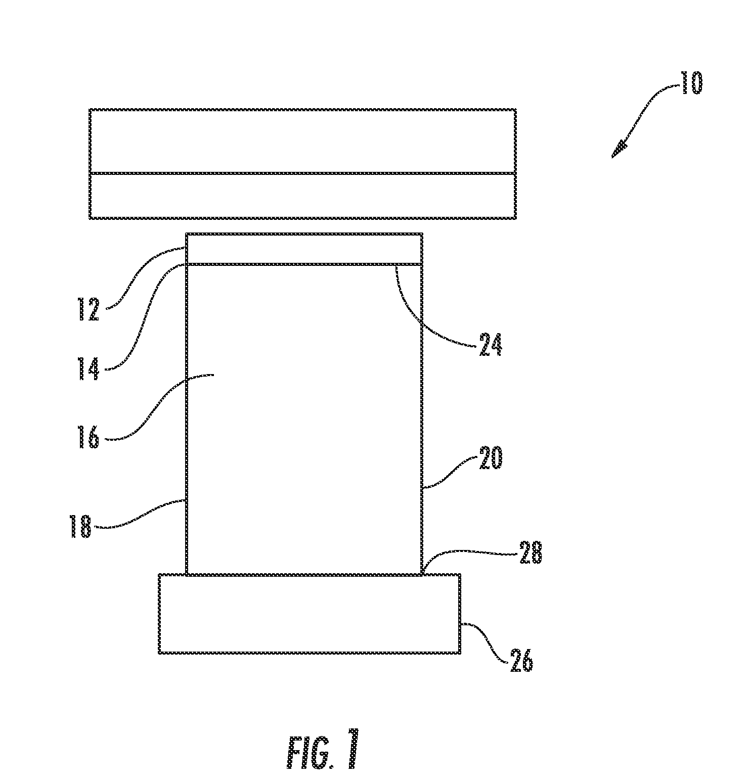
[0020]The squealer tip 12 may be attached to a radially outward tip 14 of a turbine blade 10. The turbine blade 10 may be formed from a generally elongated airfoil 16 having a leading edge 18, a trailing edge 20, the tip 14 at a first end 24, a root 26 coupled to the blade 10 at an end 28 gener...


PUM


Abstract

A turbine blade having a squealer tip coupled to a radially outer end of the turbine blade that is usable in a gas turbine engine is disclosed. The squealer tip may require less cooling air and may therefore be more efficient than conventional configurations. The squealer tip may be formed from one or more materials such as oxide dispersion strengthened alloys and FeCrAl alloys. The squealer tip may be formed from a plurality of segmented tips extending radially outward and spaced apart from each other. For example, the squealer tip may be formed from two rails extending radially outward and spaced apart from each other. The two rails may be formed from outer and inner rails that each form a continuous ring. The squealer tip may be attached to the tip with a transient liquid phase bond or an additive manufacturing process, such as, a selective laser melting process.

Description

FIELD OF THE INVENTION[0001]This invention is directed generally to turbine blades, and more particularly to tip sealing systems for turbine blades.BACKGROUND[0002]Typically, gas turbine engines include a compressor for compressing air, a combustor for mixing the compressed air with fuel and igniting the mixture, and a turbine blade assembly for producing power. Combustors often operate at high temperatures that may exceed 2,500 degrees Fahrenheit. Typical turbine combustor configurations expose turbine blade assemblies to these high temperatures. As a result, turbine blades must be made of materials capable of withstanding such high temperatures. In addition, turbine blades often contain cooling systems for prolonging the life of the blades and reducing the likelihood of failure as a result of excessive temperatures.[0003]Typically, turbine blades are formed from a root portion at one end and an elongated portion forming an airfoil that extends outwardly from a platform coupled to ...

Claims


Application Information

Patent Timeline
IPC IPC(8): F01D5/18F01D5/30F01D5/14
CPCF01D5/20F05D2230/31F05D2230/234F05D2230/22B33Y80/00
Inventor JAMES, ALLISTER W.KULKARNI, ANAND A.
Owner SIEMENS ENERGY INC
Why Eureka
Try Eureka