Real-time quality monitoring device and method for selective laser melting processing process

A laser selective melting and processing technology, applied in the field of additive manufacturing, can solve the problems of inability to monitor powder bed, limited field of view and acquisition rate of two-color thermometer, limited resolution, etc.

Inactive Publication Date: 2018-11-13
西安智造人企业管理合伙企业(有限合伙)
View PDF13 Cites 40 Cited by
  • Summary
  • Abstract
  • Description
  • Claims
  • Application Information

AI Technical Summary

Problems solved by technology

However, there are limitations in the specific use of these existing technologies
A purely industrial camera can only monitor the information of the flatness of the powder during powder spreading, capture the powder spreading defects or observe the spheroidization phenomenon after printing. The infrared thermal imaging camera is often limited by the resolution to observe the defects; the two-color thermometer is limited by the field of view and The acquisition rate cannot be developed towards closed-loop control; in addition, when the coaxial optical path is used alone to monitor the molten pool, only real-time data of the molten pool can be monitored, and other system problems such as the powder bed cannot be monitored

Method used


Image

  • Real-time quality monitoring device and method for selective laser melting processing process
  • Real-time quality monitoring device and method for selective laser melting processing process
  • Real-time quality monitoring device and method for selective laser melting processing process

Examples


Embodiment Construction

[0034] The present invention will be further described below in conjunction with the accompanying drawings.

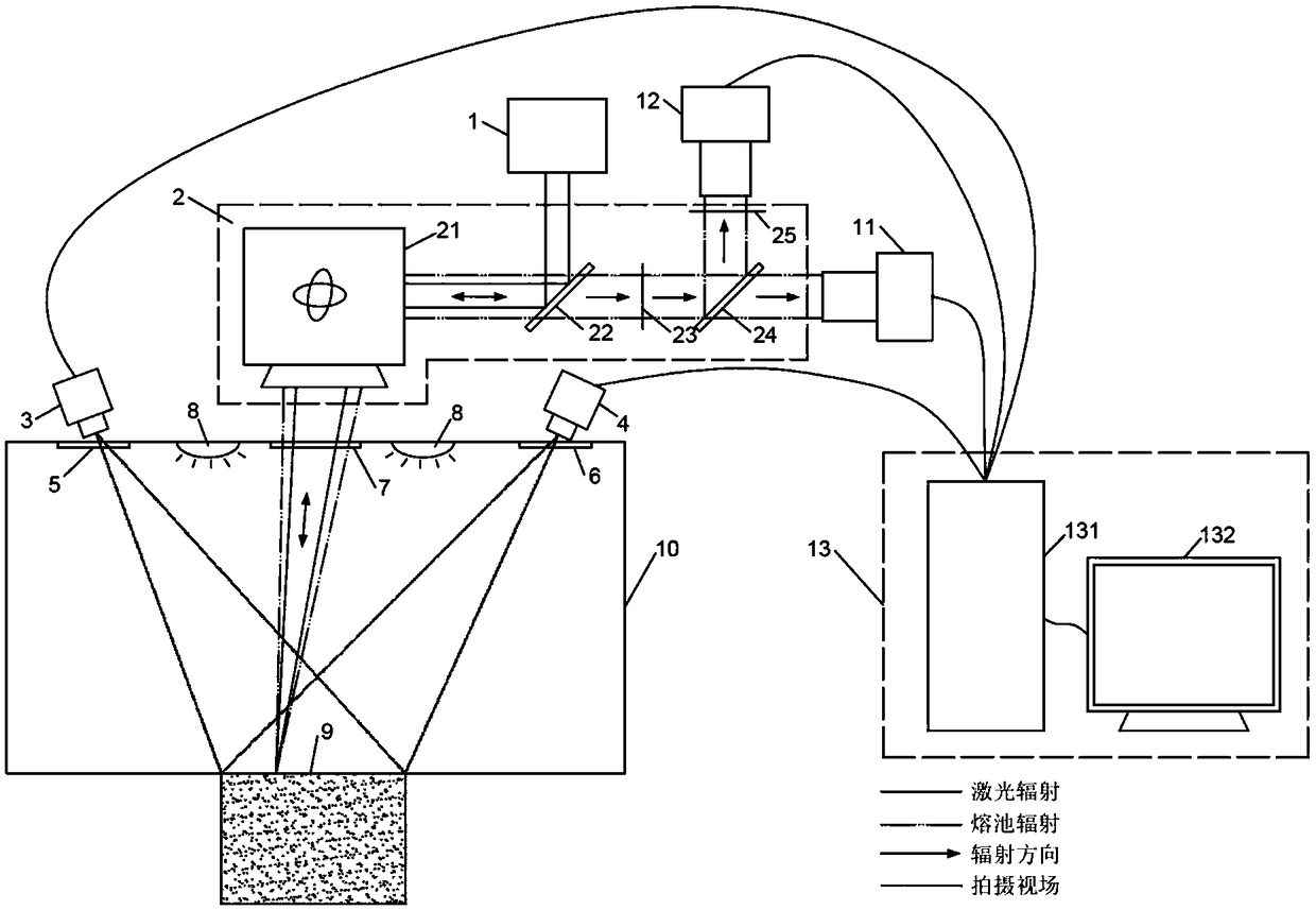
[0035] see figure 1 , a real-time quality monitoring device for laser selective melting processing, comprising a molding chamber 10, a plurality of LED light sources 8 are arranged on the inner surface of the top of the molding chamber 10, a molding cylinder 9 is placed on the bottom of the molding chamber 10, and a molding cylinder 9 is arranged outside the molding chamber 10 There are industrial camera 3, infrared thermal imager 4, laser 1, photodiode 12 and high-speed camera 11, the front end of photodiode 12 is provided with filter 25, industrial camera 3 and infrared thermal imager 4 are irradiated from the top of molding chamber 10 to form The upper surface of the cylinder 10, the laser 1, the photodiode 12 and the high-speed camera 11 photograph the upper surface of the molding cylinder 10 through the coaxial optical path 2, and the laser emitted by the laser 1 ...


PUM


Abstract

The invention discloses a real-time quality monitoring device and method for a selective laser melting processing process. Advantages of non-contact measurement means such as an industrial camera, aninfrared thermal imager, a high-speed camera and a photodiode are comprehensively utilized, and a set of complete monitoring method is formed. Through the on-line monitoring method combining an off-axis on-line monitoring device with a coaxial on-line monitoring device, the working condition of a printing work plane can be captured, and real-time molten pool data can also be collected. The meltingand condensation processes of metal powder can be monitored in a microcosmic manner, and a printer system and a workpiece layer-by-layer quality can also be monitored in a macroscopic manner. The industrial camera is adopted to monitor powder bed defects and printing defects, and the infrared thermal imager tracks the scanning path and captures the thermal stress; and the high-speed camera observes the geometrical morphology of a molten pool, and the photodiode captures the radiation strength of the molten pool. The process marks are made to correspond to printing process parameters, and on-line monitoring of the selective laser melting processing process can be realized more effectively.

Description

technical field [0001] The invention belongs to the field of additive manufacturing, and in particular relates to a real-time quality monitoring device and method for laser selective melting processing. Background technique [0002] Laser selective melting technology is an advanced laser additive manufacturing technology developed based on the basic principle of prototype manufacturing technology. The three-dimensional digital model of the part is sliced ​​and layered by special software, and after obtaining the profile data of each section, the high-energy laser beam is used to selectively melt the metal powder layer by layer according to the profile data, and the accumulated powder is melted and solidified layer by layer by spreading powder layer by layer way to manufacture three-dimensional solid parts. [0003] Laser selective melting is a "personalized" processing method, and it is difficult to guarantee a stable and consistent supply of raw material powder. There are ...

Claims


Application Information

Patent Timeline
Patent Type & Authority Applications(China)
IPC IPC(8): B22F3/105B33Y10/00B33Y50/02B33Y30/00
CPCB22F3/003B33Y10/00B33Y30/00B33Y50/02B22F10/00B22F10/38B22F12/49B22F12/42B22F12/90B22F10/28Y02P10/25
Inventor 成星周鑫胡金海贺一轩高赟李小涛张咪咪
Owner 西安智造人企业管理合伙企业(有限合伙)
Why Eureka
Try Eureka