Transfer apparatus

a technology of transfer apparatus and transfer arm, which is applied in the direction of gearing, charge manipulation, furnaces, etc., can solve the problems of increasing the manufacturing cost, affecting the clean environment, and limited movable range of the arm mechanism, so as to reduce the generation of dust and simplify the structure of the driving arm

Inactive Publication Date: 2017-03-30
DAIHEN CORP
View PDF1 Cites 4 Cited by
  • Summary
  • Abstract
  • Description
  • Claims
  • Application Information

AI Technical Summary

Benefits of technology

[0008]According to an aspect of the present disclosure, the driving arm is connected to the driven arm via the gear mechanism, which suppresses dust generation compared to the case of using a belt.
[0009]Moreover, one end of the driving arm is connected to the drive source while the driving arm houses no motor therein, which eliminates the need for the driving arm to have a hollow structure, and thereby simplifies the structure of the driving arm.

Problems solved by technology

In the vacuum transfer robot of a belt slidable type with the use of a belt mechanism and a guide, a belt is exposed to a vacuum region, and dust (particles) generated from the belt harms the clean environment.
The first arm has a complicated structure, which increases the manufacturing cost thereof.
If the driving arm and the driven arm interfere with each other, the movable range of the arm mechanism is limited to an area in which they do not interfere with each other.

Method used


Image

  • Transfer apparatus
  • Transfer apparatus
  • Transfer apparatus

Examples


Embodiment Construction

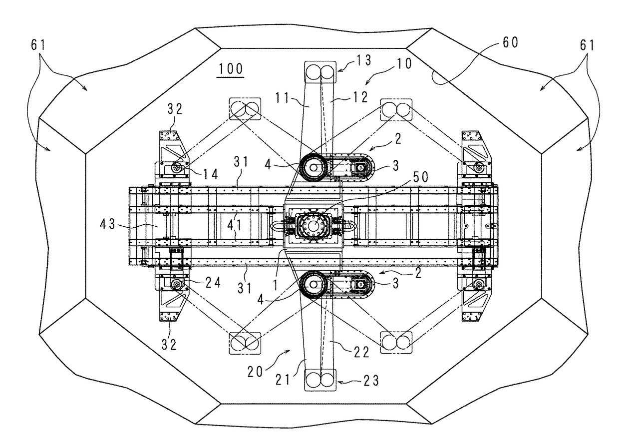
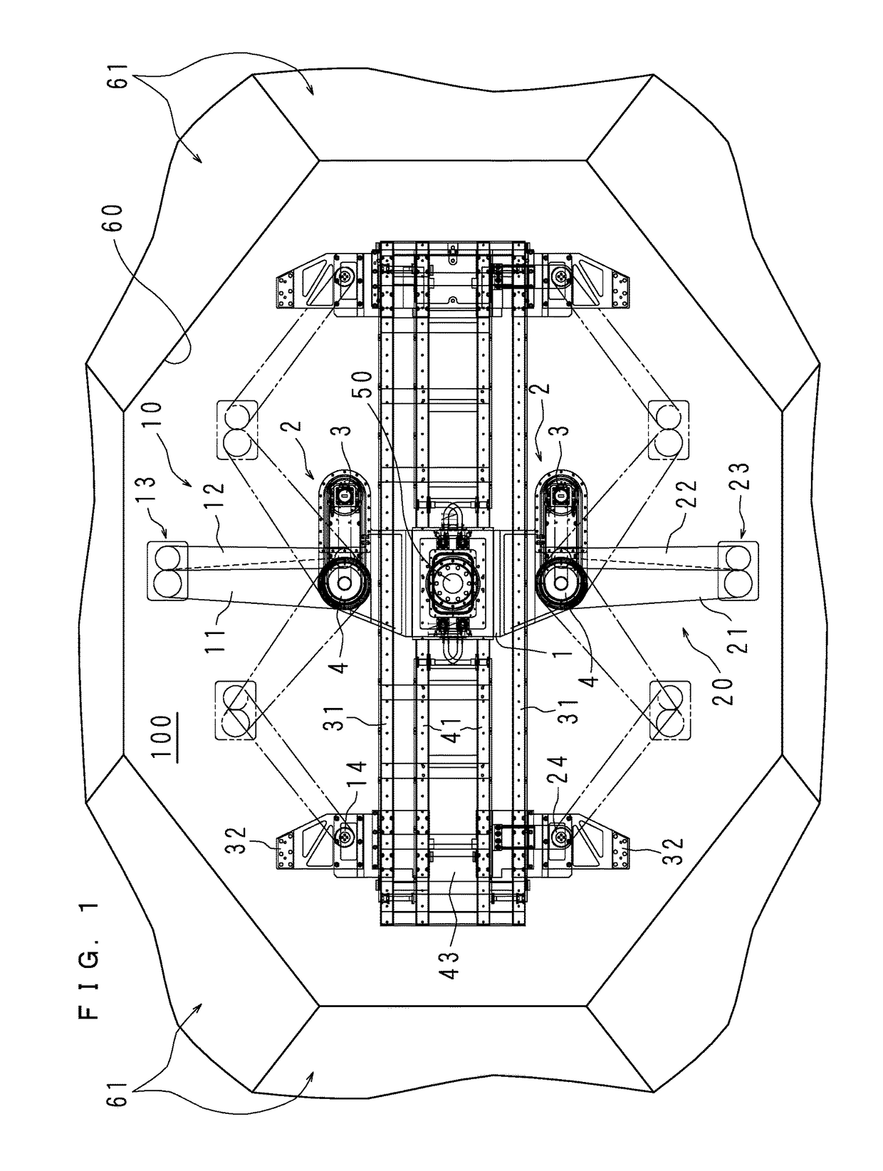
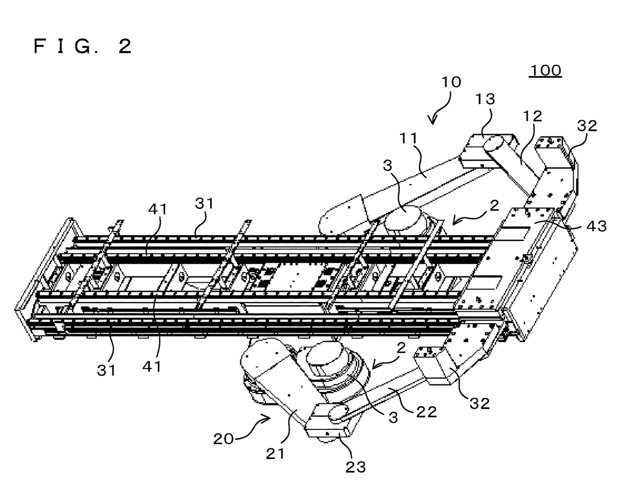
[0024]A transfer apparatus 100 according to an embodiment thereof will be described below with reference to the drawings. FIG. 1 is a plan view schematically illustrating the transfer apparatus 100, FIG. 2 is a perspective view schematically illustrating the transfer apparatus 100, and FIG. 3 is a section view schematically illustrating the transfer apparatus 100. In FIG. 1, the long-dashed double-short-dashed lines indicate a first arm mechanism 10 and a second arm mechanism 20 moved from the middle in the horizontal direction in FIG. 1 to the right or left side. A first hand holding member 33 which will be described later is not illustrated in FIGS. 1 and 2.

[0025]As illustrated in FIGS. 1 and 2, the transfer apparatus 100 has a laterally-long shape extending in the horizontal direction, and is housed in a housing 60 of a polygonal shape in plan view. Each wall surface of the housing 60 constitutes each wall surface of multiple chambers 61. A substrate processing device (not illust...


PUM


Abstract

A transfer apparatus capable of suppressing dust generation and reducing the manufacturing cost thereof is provided.
In a transfer apparatus including a transfer unit which moves on a rail to transfer an object and an arm mechanism which transmits the power from a drive source to the transfer unit, the arm mechanism includes a rotatable driving arm with one end thereof connected to the drive source, a driven arm with one end thereof connected to the transfer unit, and a gear mechanism which connects the other end of the driven arm to the other end of the driving arm and transmits the rotation of the driving arm to the driven arm.

Description

CROSS-REFERENCE TO RELATED APPLICATIONS[0001]This Nonprovisional application claims priority under 35 U.S.C. §119(a) on Patent Application No. 62 / 234,891 filed in U.S. on Sep. 30, 2015, the entire contents of which are hereby incorporated by reference.FIELD[0002]The present technology relates to a transfer apparatus that transfers an object.BACKGROUND AND SUMMARY[0003]A vacuum transfer robot of a belt slidable type with the use of a belt mechanism and a guide is disclosed already in the past. A vacuum transfer robot of an arm slidable type is also disclosed.[0004]In the vacuum transfer robot of a belt slidable type with the use of a belt mechanism and a guide, a belt is exposed to a vacuum region, and dust (particles) generated from the belt harms the clean environment.[0005]The vacuum transfer robot of an arm slidable type comprises a large first arm having a hollow structure capable of housing a motor and a speed reducer, and a second arm connected to the first arm and a sliding m...

Claims


Application Information

Patent Timeline
Patent Type & Authority Applications(United States)
IPC IPC(8): B65G49/06B25J18/04H01L21/677B25J5/02
CPCB65G49/067B25J5/02Y10S901/25H01L21/67742H01L21/67745B25J18/04B65G47/902B65G47/907B65G2249/02B65G47/90B65G49/061B65G2201/022F16H1/06H01L21/67739H01L21/67772
Inventor TAKARABE, SAYAKOIURA, JUN
Owner DAIHEN CORP
Why Eureka
Try Eureka