Attraction device, method for producing attraction device, and vacuum processing device

a vacuum processing device and attraction electrode technology, applied in electrostatic holding devices, metal-working machine components, manufacturing tools, etc., can solve the problems of unresolved positional relationship between the attraction electrode pattern and the contact part of the rear surface of the substrate, unsatisfactory attraction condition, and relatively large attraction force, so as to reduce the generation of dust and control the attraction force of the attraction device to be uniform

Active Publication Date: 2020-07-21
ULVAC INC
View PDF10 Cites 0 Cited by
  • Summary
  • Abstract
  • Description
  • Claims
  • Application Information

AI Technical Summary

Benefits of technology

[0015]The present invention has been made to solve the aforementioned problems associated with the conventional art. An object of the present invention is to provide a technique for suppressing dust generation at the time of attraction and detachment of an object to be attracted, and for enabling control of the attraction force of the attraction device to be uniform.

Problems solved by technology

Furthermore, the positional relationship between the attraction electrode pattern and the contact part of the rear surface of the substrate has not been addressed.
Accordingly, the resistance value or distance differs between the attraction electrode and the substrate, and the attraction condition has not been uniform.
Furthermore, in an area where an attraction electrode exists directly below the contact part between the substrate and the attraction surface, the attraction force is relatively large, and the material of the rear surface of the substrate or the surface of the attraction device peels off.
The foregoing is a cause of process failure due to dust generation.
As well, the attraction force due to a residual electric charge on the attraction surface becomes uneven, the substrate vibrates during transportation thereof and breakage of the substrate may be occurred.
Moreover, the non-uniformity of the residual attraction force on the attraction surface affects the attraction condition while the process is repeated.
In particular, temperature control per a substrate is inconsistent. and even when the residual attraction force is removed from the attraction surface by, for example, reverse polarity voltage application, it is difficult to completely remove the residual attraction force.
Accordingly, a decrease in the reliability, such as, in the yield of the production process, has been a problem.
However, the problem of this type of method has a problem that the attraction device cannot fully demonstrate the original attraction ability due to a decrease in the efficiency of heat transfer from the attraction surface to the substrate.
Another problem is that a substrate conveyance error or a decrease in the yield of each substrate can be caused by a residual attraction force, occurred by a shortened throughput time in the production process, for example.

Method used


Image

  • Attraction device, method for producing attraction device, and vacuum processing device
  • Attraction device, method for producing attraction device, and vacuum processing device
  • Attraction device, method for producing attraction device, and vacuum processing device

Examples


Embodiment Construction

[0032]Embodiments of the present invention will be described hereinbelow with reference to the drawings.

[0033]The present invention is applicable to an attraction device of a bipolar or unipolar type.

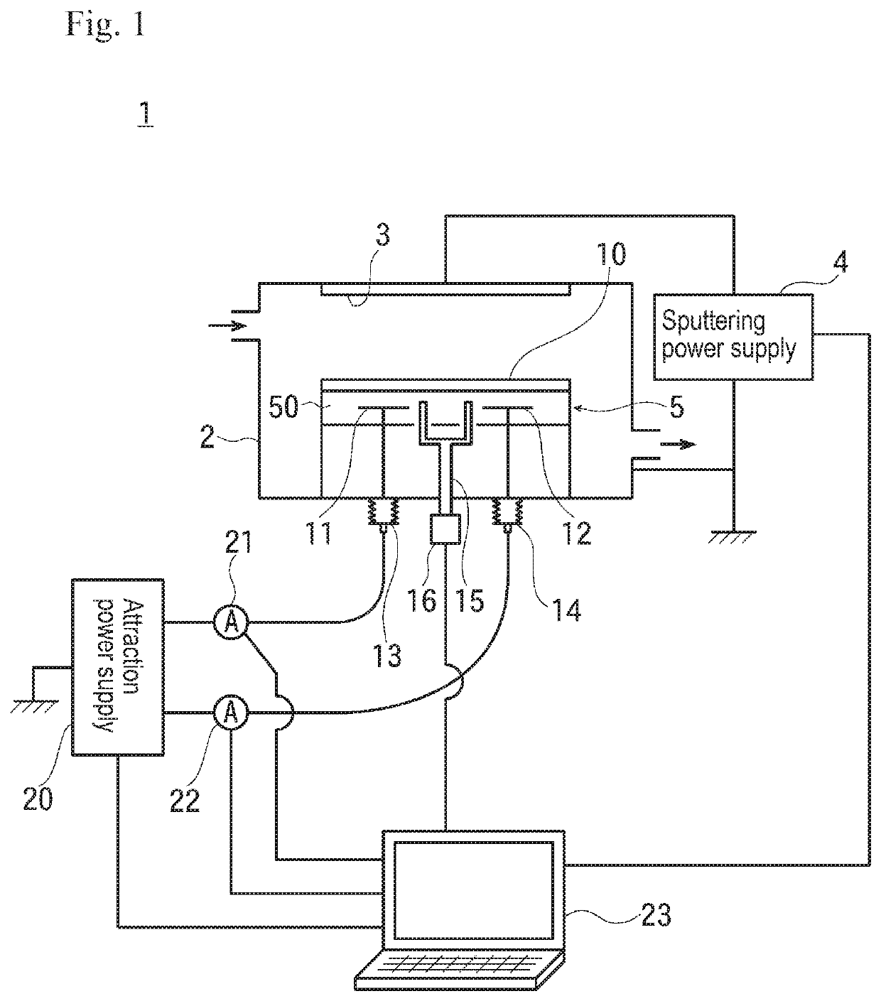
[0034]FIG. 1 is a schematic diagram illustrating a configuration of a sputtering device that is one embodiment of a vacuum processing device according to the present invention.

[0035]In FIG. 1, reference numeral 2 denotes a vacuum chamber of a sputtering device 1 according to this embodiment. This vacuum chamber 2 is connected to a vacuum evacuation system (not shown in the drawings), and is configured such that a sputtering gas is introduced into the vacuum chamber 2.

[0036]A target 3, which is a source of film formation, is disposed at the upper portion of the vacuum chamber 2.

[0037]This target 3 is connected to a sputtering power supply 4, and a negative bias voltage is applied to the target 3. The positive side of the sputtering power supply 4 is earthed together with the vacuum chamb...


PUM

PropertyMeasurementUnit
resistivityaaaaaaaaaa
volume resistivityaaaaaaaaaa

Abstract

Providing a technique for suppressing dust generation at the time of attraction and detachment of an object to be attracted, and for enabling control the attraction force of the attraction device to be uniform. The attraction device of the present invention includes a main body part having attraction electrodes within a dielectric; and an attraction part for attracting a substrate, provided on a surface of the main body part at an attraction-side. The attraction part includes a contact support part that is in contact with, and supports the substrate and a non-contact part that is not in contact with the substrate. In the attraction part, the volume resistivity of the material of the contact support part is greater than the volume resistivity of the material of the non-contact part.

Description

TECHNICAL FIELD[0001]The present invention generally relates to an attraction device that attracts and holds a substrate in vacuum ambience, and in particular, to a technique for an attraction device that attracts and holds a substrate having an insulating film on the rear surface thereof and an insulating substrate.BACKGROUND[0002]Conventionally, an electrostatic attraction device has been widely used to precisely control the temperature of a substrate in, e.g., a sputtering device. In a device that performs processing, e.g., film forming on an insulating substrate, such as glass, in vacuum ambience, an attraction device that attracts and holds the insulating substrate by a gradient force is widely used. Furthermore, when electrostatic attracting a substrate having an insulating film on the rear surface thereof, for example, a method of increasing the attraction voltage in order to enhance the attraction force is adopted.[0003]In such an attraction device, the entire surface is in ...

Claims


Application Information

Patent Timeline
Patent Type & Authority Patents(United States)
IPC IPC(8): H02N13/00H01L21/67H01L21/683B23Q3/15H01J37/32H01J37/34
CPCH01J37/32715B23Q3/15H01L21/683H01L21/6833H01L21/67253H01J37/34H02N13/00
Inventor MAEHIRA, KENFUWA, KOU
Owner ULVAC INC
Why Eureka
Try Eureka