Conveying apparatus

a technology of conveying apparatus and moving parts, which is applied in the direction of conveying, fluid-pressure actuators, transportation and packaging, etc., can solve the problems of difficult to maintain high air cleanliness inside the clean room, dust may leak together, etc., and achieve the effect of suppressing the generation of dus

Active Publication Date: 2016-05-03
MIURA COMPANY LIMITED
View PDF33 Cites 1 Cited by
  • Summary
  • Abstract
  • Description
  • Claims
  • Application Information

AI Technical Summary

Benefits of technology

[0005]It is an object of the present invention to provide a conveying apparatus capable of suppressing generation of dust.

Problems solved by technology

In the technique of the related art described above, dust such as abrasive debris may be generated from a sliding movement portion such as the motor and the roller, or this dust may leak together with a lubricant.
Therefore, it is difficult to maintain high air cleanliness inside the clean room.

Method used


Image

  • Conveying apparatus
  • Conveying apparatus
  • Conveying apparatus

Examples


Embodiment Construction

[0023]A description will now be made for embodiments of this disclosure with reference to the accompanying drawings.

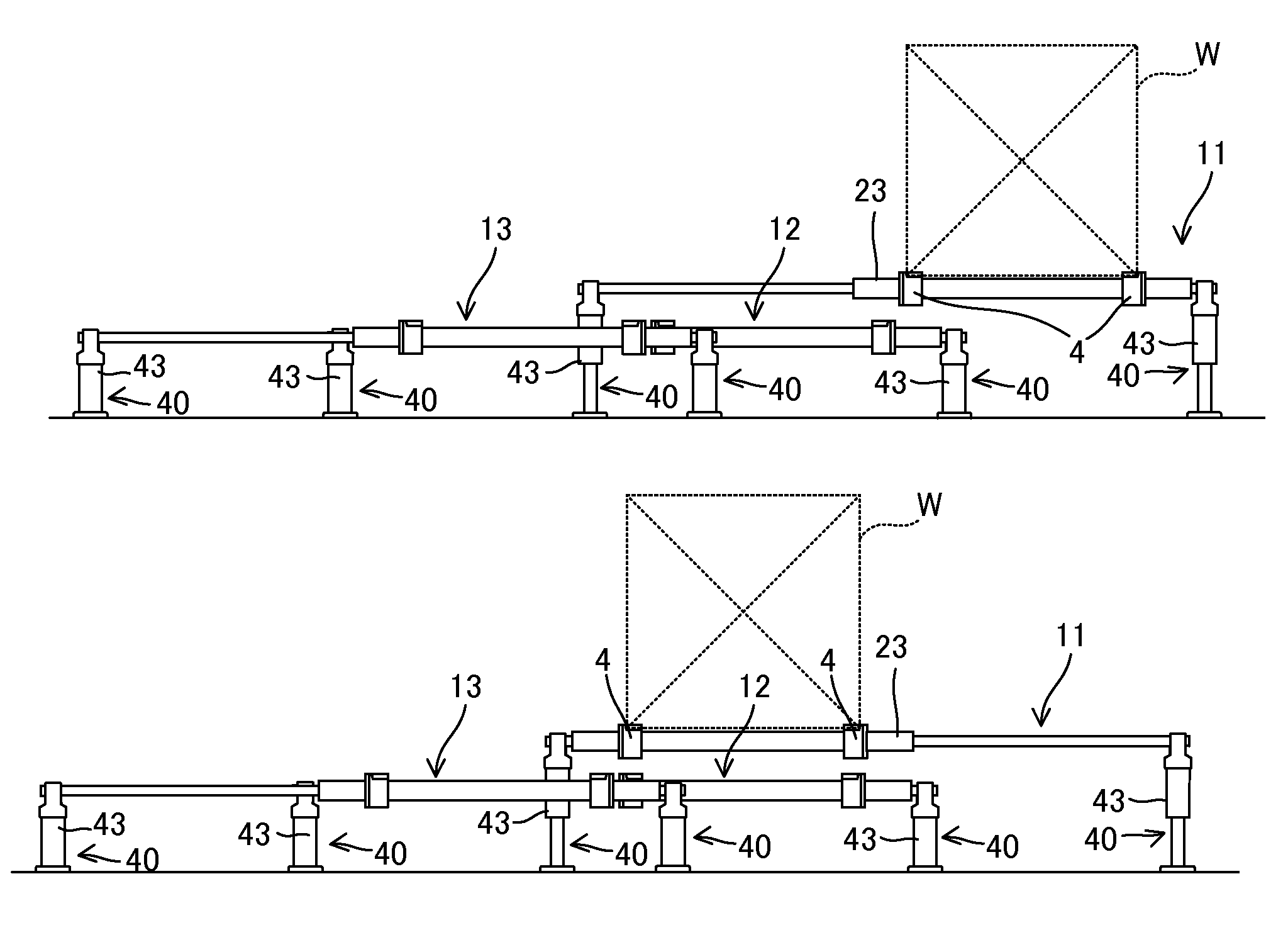
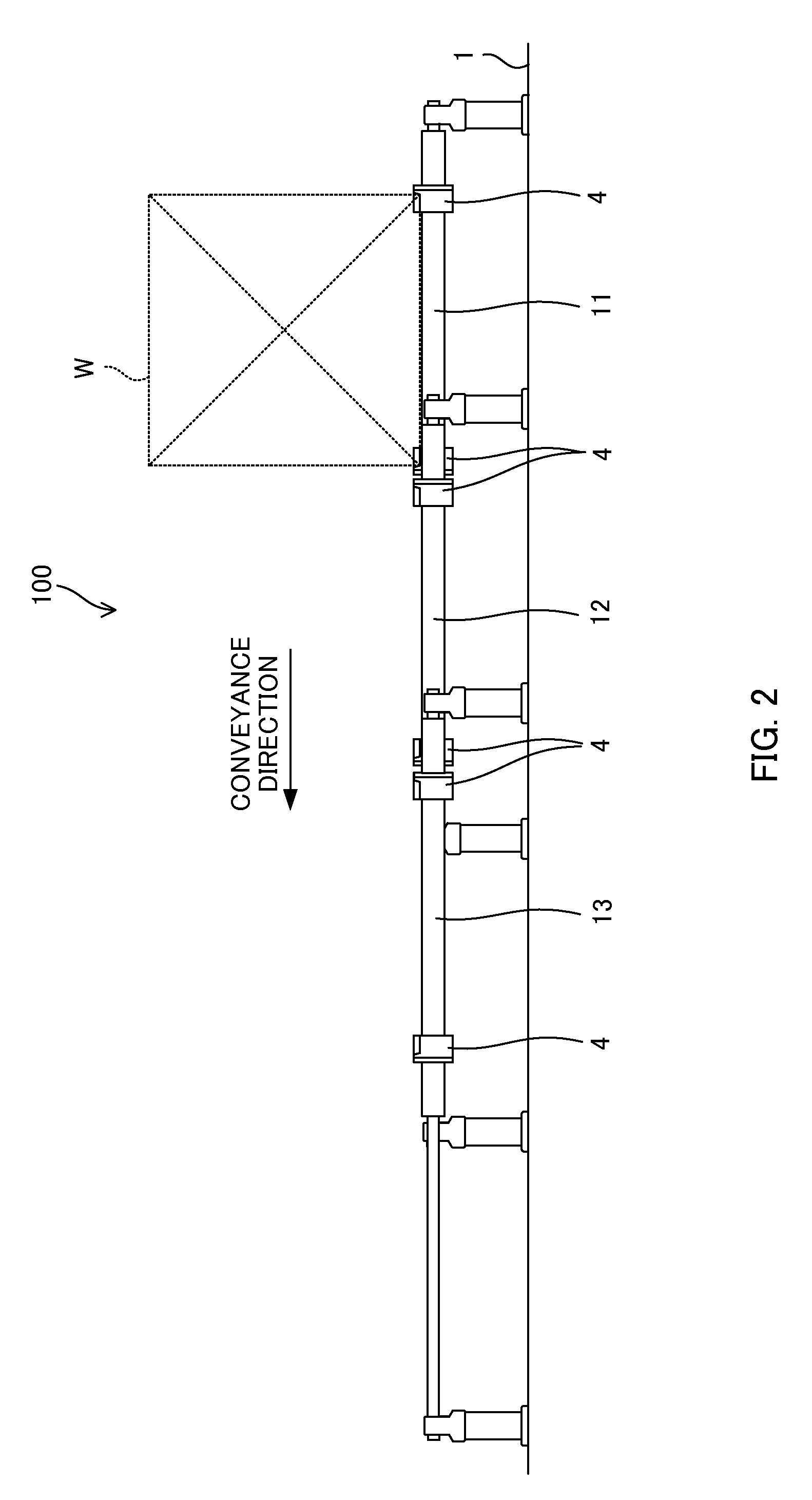
[0024]FIG. 1 is a top plan view illustrating a conveying apparatus 100 according to an embodiment of this disclosure. FIG. 2 is a side view illustrating the conveying apparatus 100 of FIG. 1 as seen from an arrow direction A. FIG. 3 is a side view illustrating the conveying apparatus 100 of FIG. 1 as seen from an arrow direction B. It is noted that a frame 2 is not illustrated in FIG. 2 intentionally for clear description purposes.

[0025]The conveying apparatus 100 is an apparatus for conveying a source material or the like in a clean room, where high air cleanliness is necessary, of a factory for manufacturing medicines, foods, and the like. The conveyed source material is approximately horizontally shifted inside a clean room while it is contained in a container or the like. In the following description, this container and the like will be referred to as a “workpiece ...


PUM


Abstract

Hydraulic cylinders of a conveying apparatus includes piston rods that extend in parallel, pistons, and cylinder tubes that have an internal pressure chamber partitioned into first and second pressure chambers. A pair of the hydraulic cylinders are arranged in parallel with an interval in a width direction of a conveyance path. The cylinder tube slidingly moves to the first pressure chamber side by supplying a hydraulic pressure to the first pressure chamber and discharging a hydraulic pressure from the second pressure chamber, and the cylinder tubes slidingly move to the second pressure chamber side by supplying a hydraulic pressure to the second pressure chamber and discharging a hydraulic pressure from the first pressure chamber. The workpiece is supported by a pair of the cylinder tubes.

Description

TECHNICAL FIELD[0001]The present invention relates to a conveying apparatus.BACKGROUND ART[0002]Medicines or foods are manufactured inside a clean room having high air cleanliness in order to avoid a foreign object from being mixed. When a typical conveying apparatus such as a conveyor belt is employed inside the clean room, the air cleanliness is degraded due to dust generation.[0003]JP9-142629A discloses a conveying apparatus designed for using in a clean room. This conveying apparatus is a belt conveyor, in which a loop-like belt is stretched between a plurality of rollers, and the belt is driven by rotating the rollers using a motor. A load is placed on the belt of the upper surface and is conveyed horizontally.SUMMARY OF INVENTION[0004]In the technique of the related art described above, dust such as abrasive debris may be generated from a sliding movement portion such as the motor and the roller, or this dust may leak together with a lubricant. Therefore, it is difficult to ma...

Claims


Application Information

Patent Timeline
Patent Type & Authority Patents(United States)
IPC IPC(8): B65G25/04B65G25/02F15B15/14
CPCB65G25/02F15B15/14B65G25/04
Inventor MIURA, TAKAO
Owner MIURA COMPANY LIMITED
Why Eureka
Try Eureka