Axial Air Gap Type Electric Motor

a technology of electric motor and air gap, which is applied in the direction of dynamo-electric machines, electrical equipment, magnetic circuit shapes/forms/construction, etc., can solve the problems of iron core dropping from the bobbin, iron core not being correctly inserted, and laminated layer thickness not being fixed

Active Publication Date: 2017-03-30
HITACHI IND EQUIP SYST CO LTD
View PDF2 Cites 2 Cited by
  • Summary
  • Abstract
  • Description
  • Claims
  • Application Information

AI Technical Summary

Benefits of technology

The present invention allows for easy adjustment of the size of a laminated iron core based on the thickness of the metal plate-like member that forms it. This results in a better fit and maintained shape of the laminated iron core.

Problems solved by technology

Therefore, in the case where the laminated iron core used in the stator of the axial air gap type electric motor is manufactured, even when a fixed number of the core members are laminated, the laminated layer thickness may not be fixed.
In the case where the stator core to be manufactured is configured, such as by inserting the laminated iron core, as a prismatic body, into a tubular bobbin, and then, winding a coil around the outer periphery of the bobbin, there is a problem that, when the laminated layer thickness of the iron core becomes large, the laminated core member is buckled so that the iron core cannot be correctly inserted.
On the other hand, there is such a problem that, when the laminated layer thickness of the iron core becomes small, the iron core drops from the bobbin.
This problem can cause loss of productivity of the axial air gap type electric motor.
Therefore, there is a problem that, when the cutting dimension and the number of laminated layers are controlled by measuring the plate thickness of the member always used, the productivity is significantly decreased.

Method used


Image

  • Axial Air Gap Type Electric Motor
  • Axial Air Gap Type Electric Motor
  • Axial Air Gap Type Electric Motor

Examples


first embodiment

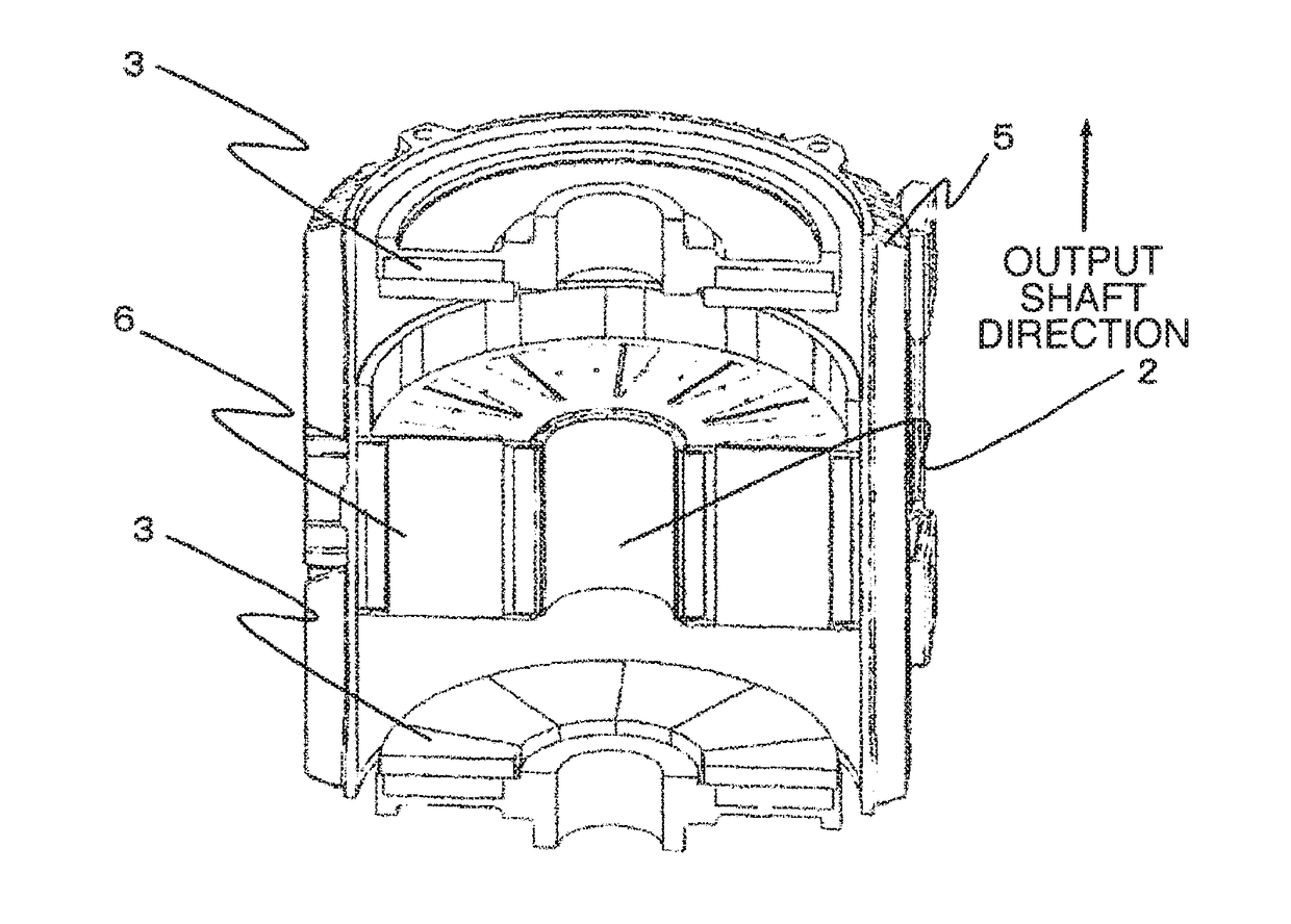
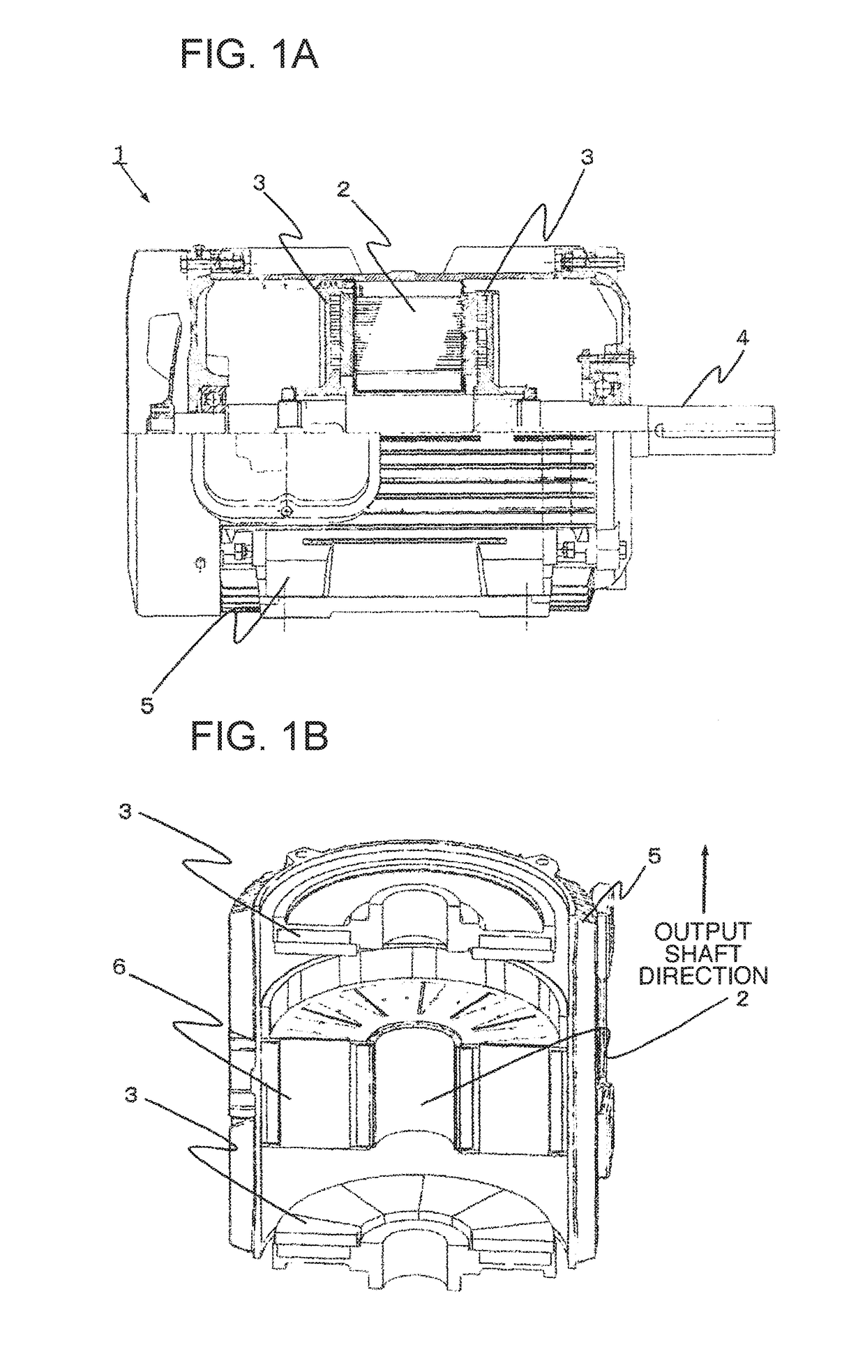
[0022]FIG. 1(a) shows an overall configuration of an axial air gap type electric motor 1 of a first embodiment to which the present invention is applied, and FIG. 1(b) is a cross sectional view of a main portion of the axial air gap type electric motor. The axial air gap type electric motor 1 includes, in the inside of a substantially tubular housing 5, a stator 2, a rotor 3 fixed to a rotating shaft 4 and rotated together with the rotating shaft 4, output side and opposite-to-output side end brackets each connected to the rotating shaft 4 via bearings, a cooling fan passing through the opposite-to-output side end bracket to be connected to the end portion of the rotating shaft 4 and rotated together with the rotating shaft 4, and a fan cover guiding cooling air generated by the cooling fan to the outer peripheral side of the housing 5.

[0023]As shown in FIG. 1(b), the axial air gap type electric motor 1 has a two rotor armature structure in which the ring-shaped stator 2, having mag...

second embodiment

[0033]Next, a second embodiment is described. FIG. 5 shows the cross section of the end portion of the laminated iron core 8 of the second embodiment. In the present embodiment, a straight line portion (core members 10a), for increasing or decreasing a predetermined laminated layer number of the plate-like core members 10a laminated in straight line shape corresponding to the cutting and lamination direction of the core members 10a, is formed on the inner peripheral side with respect to the rotating shaft 4 of the axial air gap type electric motor 1, that is, on the side on which the cutting width of the laminated iron core 8 is reduced (the side of the rotating shaft).

[0034]Even in this configuration, it is possible to easily adjust the lamination thickness of the laminated iron core 8 by increasing or decreasing the laminated layer number of the core members 10a. Thereby, in the axial air gap type electric motor, a stator with high precision can be obtained, and thereby, it is pos...

application examples

[0037]Finally, application examples in which the first to third embodiments are combined are described. FIG. 7(a) to FIG. 7(d) each show the cross section of the end portion in an application example of the laminated iron core 8. In each of FIG. 7(a) to FIG. 7(d), each of portions indicated by dotted line circles shows the straight line portion (core members 10a) for adjusting the lamination thickness.

[0038]FIG. 7(a) shows a configuration in which the core members 10a laminated in straight line are provided at the end portion on the outer peripheral side with respect to the rotating shaft 4 of the axial air gap type electric motor 1, that is, the side on which the cutting width of the core member is large, and also at the end portion of the inner periphery side with respect to the rotating shaft 4, that is, the side on which the cutting width of the core member is small.

[0039]Similarly, FIG. 7(b) shows a configuration in which the core members 10a laminated in straight line are prov...


PUM


Abstract

The purpose of the present invention is to efficiently cope with the plate thickness deviation of a laminated iron core in an axial air gap type electric motor. An axial air gap type electric motor comprises: a stator formed by arranging stator cores around a rotating shaft in a ring shape, said stator cores each including a laminated iron core that is a prismatic body formed by laminating metal plate-like members in a radial direction of the rotating shaft, a tubular bobbin that has an inner diameter into which the laminated iron core is inserted, and a coil that is wound on the extension of the outer diameter of the laminated iron core; and at least one rotor plane-facing the rotating shaft direction end section of the stator with a predetermined air gap interposed therebetween. The laminated iron core includes: a portion (core member) formed by continuously laminating the metal plate-like members, the widths of which increase in a rotational direction of the rotating shaft from the rotating shaft center toward a radial direction; and a portion (core member) formed by continuously laminating the metal plate-like members, the widths of which are substantially equal.

Description

TECHNICAL FIELD[0001]The present invention relates to an axial air gap type electric motor, and more particularly to an axial air gap type electric motor in which a laminated iron core is used in a stator.BACKGROUND ART[0002]In recent years, in order to improve the efficiency of an electric motor, a permanent magnet (PM) motor has been widely used. A neodymium magnet is a magnet having a higher efficiency than others but involves problems in terms of cost and the like because it contains a rare metal (rare earth).[0003]As a magnet containing no rare metal, a magnet containing a ferrite magnet is generally used. However, in a radial air gap type electric motor having an air gap in the same direction as the rotating shaft, a ferrite magnet needs to be arranged along the rotation direction of the output shaft, and hence, in order to obtain the same performance as that of the neodymium magnet, it is necessary to increase the size of the electric motor to increase the volume of the ferri...

Claims


Application Information

Patent Timeline
Patent Type & Authority Applications(United States)
IPC IPC(8): H02K1/14H02K1/18
CPCH02K1/182H02K1/14H02K1/18H02K21/24H02K15/02H02K2203/12
Inventor SAKAI, TORUTAKAHASHI, DAISAKUSAKURAI, JUNTAKAHASHI, SHUUICHITOKOI, HIROOKIMAEDA, YUKIMASA
Owner HITACHI IND EQUIP SYST CO LTD
Why Eureka
Try Eureka