
Ventilation system with mechanical ventilation and extracorporeal blood gas exchange

a ventilation system and extracorporeal technology, applied in the field of ventilation systems, can solve the problems of inability to fully automate and coordinate the system is hardly suitable for a largely automated, coordinated operation of both systems, and is susceptible to instabilities and complications in the operation, so as to reduce the degree of extracorporeal oxygenation, reduce the flow of blood, and reduce the degree of extracorporeal suppor

Active Publication Date: 2017-04-06
HAMILTON MEDICAL AG
View PDF11 Cites 7 Cited by
  • Summary
  • Abstract
  • Description
  • Claims
  • Application Information

AI Technical Summary

Benefits of technology

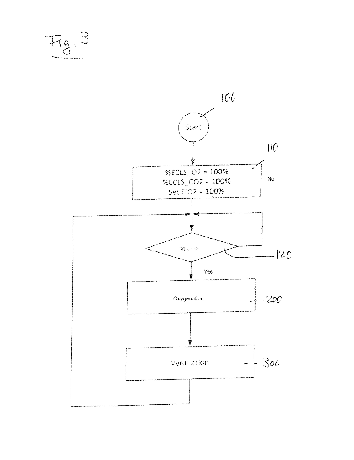
The patent describes a method for weaning a patient from a mechanical ventilation system using an extracorporeal blood gas exchange device (ECLS). The method involves gradually reducing the level of support provided by the ECLS device in favor of mechanical ventilation. This is done by adjusting the degree of extracorporeal oxygenation and the maximum positive end-expiratory pressure (PEEP) in mechanical ventilation. The method ensures that the patient is weaned off the mechanical ventilation system as quickly and safely as possible while maintaining effective oxygenation and carbon dioxide removal.

Problems solved by technology

However, it can be seen that in cooperation of the two partial systems, the ventilation system is susceptible of instabilities and complications in operation, as both the partial system ECLS as well as the partial system positive-pressure ventilation will try to counteract a too low level of support—expressed by the control parameter transferred from the respective other partial system.
This leads to competition of the two partial systems, with the tendency of a too strong reaction to changes.
Therefore, this system is hardly suitable for a largely automated, coordinated operation of both systems in the scope of a therapy.

Method used


Image

  • Ventilation system with mechanical ventilation and extracorporeal blood gas exchange
  • Ventilation system with mechanical ventilation and extracorporeal blood gas exchange
  • Ventilation system with mechanical ventilation and extracorporeal blood gas exchange

Examples


Embodiment Construction

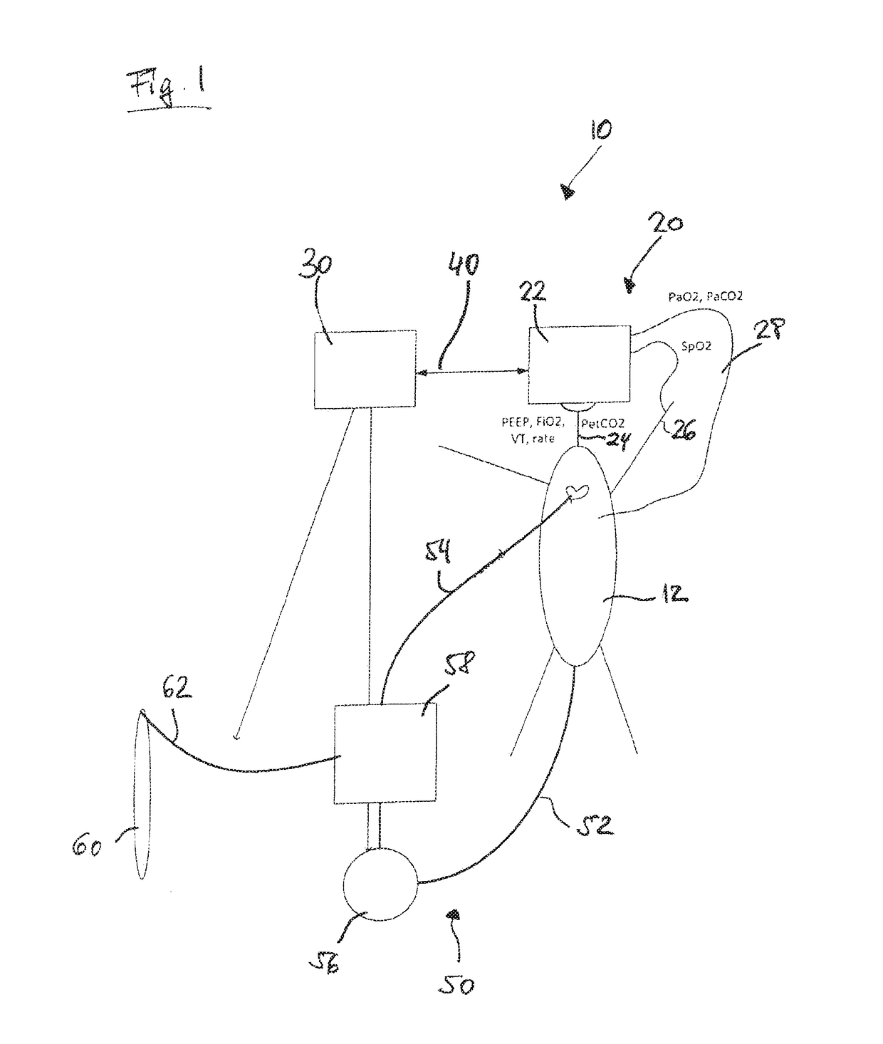
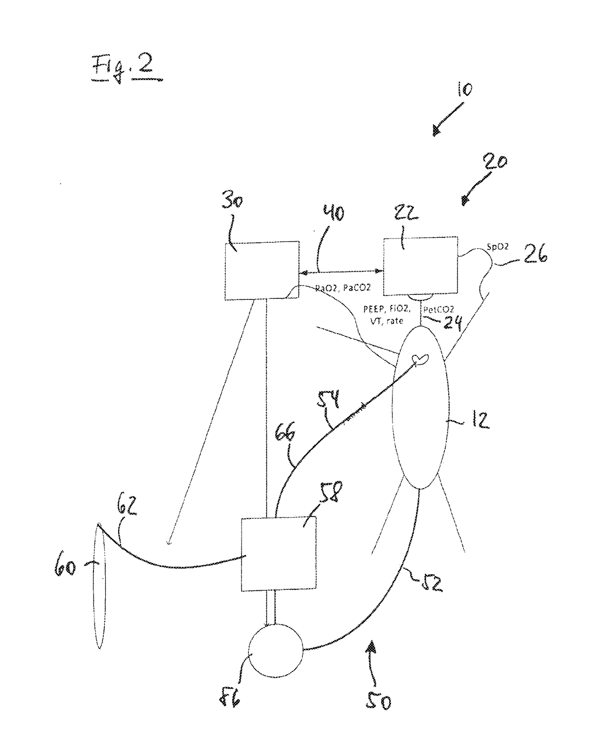
[0059]FIG. 1 shows in a schematic and highly simplified view a ventilation system 10 according to the invention, comprising a device 20 for mechanical ventilation designed as positive-pressure ventilation device, and an ECLS device 50. The ventilation device 20 comprises a ventilator 22 shown merely schematically in FIG. 1. The ventilator 22 is connected, via a conduit system 24 not shown in more detail, to the airway of a patient (illustrated schematically in FIG. 1 and designated 12). Via the conduit system 22, the ventilator 22 supplies pressurized air to the airway of the patient 12 during inspiration phases and discharges air from the patient's airway during expiration phases. During ventilation, the conduit system 22 permanently has a positive end-expiratory pressure PEEP applied thereto. Added to this pressure, during the inspiration phases, is an inspiration pressure Pinsp that is also applied by the ventilator (and which as a rule changes during the inspiration cycle). Duri...


PUM


Abstract

A system for supporting the blood gas exchange by means of mechanical ventilation and extracorporeal blood gas exchange comprises a ventilation device for mechanical ventilation of the lungs of a patient, and an ECLS device for the extracorporeal blood gas exchange, wherein the ventilation system is designed to perform mechanical respiratory support by the ventilation device on the one hand and an extracorporeal blood gas exchange by the ECLS device on the other hand in coordinated, automated manner in order to support the gas exchange in the blood circulation of the patient, wherein the ECLS device sets a level of the extracorporeal blood gas exchange, and the ventilation device, on the basis of the level of the extracorporeal blood gas exchange set by the ECLS device, adjusts in automated manner to a level of the mechanical respiratory support.

Description

BACKGROUND[0001]Technical Field[0002]The present invention relates to a ventilation system comprising a device for mechanical ventilation, in particular positive-pressure ventilation, of the lungs of a patient, and an ECLS device for extracorporeal blood gas exchange.[0003]Description of the Related Art[0004]The system is designed to perform mechanical respiratory support by means of the device for mechanical ventilation on the one hand, and extracorporeal blood gas exchange, in particular oxygenation / ventilation, by the ECLS device on the other hand, in coordinated, automated manner in order to support the gas exchange in the blood circulation of the patient. The system is designed specifically for the intensive care of patients, in particular for supporting the pulmonary function and the blood gas exchange, respectively, when, in the course of intensive treatment with mechanical ventilation of a patient, a development towards situations sets in in which mechanical ventilation alon...

Claims


Application Information

Patent Timeline
Patent Type & Authority Applications(United States)
IPC IPC(8): A61M1/16A61M16/00
CPCA61M1/1601A61M16/0003A61M1/1698A61M2205/3331A61M2016/003A61M2230/202A61M2230/005A61M2016/0027A61M2230/205A61M16/00A61M2016/1025A61M2016/103A61M2230/435A61M2230/432A61M16/022
Inventor LAUBSCHER, THOMASNOVOTNI, DOMINIK
Owner HAMILTON MEDICAL AG
Learn More