Door Anti-slamming device

Active Publication Date: 2017-04-06
HOPKINS NICOLAS LEITH
View PDF18 Cites 1 Cited by
  • Summary
  • Abstract
  • Description
  • Claims
  • Application Information

AI Technical Summary

Benefits of technology

The invention is a device with a key feature that helps control the pressure and avoid slamming a door. Increasing the length of the device's tip, adding material to the tip, and adjusting the orifice allows for greater resistance to external forces and changing conditions. The use of fluid as a material offers advantages over air, and the absence of complicated mechanical parts lowers manufacturing costs and reduces maintenance requirements.

Problems solved by technology

For example, shipping container doors are very heavy and large.
At sea, or even at port, wind can catch a door and quickly cause it to slam against the container walls or entrance, even if a person or safety mechanism is intended to temporarily hold it in place.
If a person is inadvertently in the path of the door as it slams against a surface, the person could be severely injured.
This can lead to injury, or in severe cases broken bones or even complete amputation of finger(s).
Secondly, even if no one is near the door and therefore injury is not a concern, a slamming door can still cause damage to the door or door frame, especially if it happens many times or if there is an extreme force applied.
A slamming door can also be a rather horrible noise to hear, and most people would want to avoid the situation where possible.
There are anti-door slamming devices already on the market but these can have a number of problems as outlined below.Many devices can be overly big, cumbersome and / or unsightly due to their requirement to house large components or the need to be positioned in a particular area to achieve the desired function.Many door anti-slamming devices which are configured to withstand more extreme forces being applied can also be overly expensive due to large componentry or systems.Yet other smaller devices can be simply inadequate to handle more extreme forces.
For example, devices which primarily rely on a biasing means such as a spring to slow a slamming door do not work well.Many current devices can be overly complicated from a mechanical perspective, and be prone to damage or faulty parts.Often the intended impact point of the device is disadvantageously configured to slow a very fast moving peripheral part of the pivoting door.Many types of door anti-slamming devices can be frustrating to use as the systems employed can prevent a person from easily closing the door at a normal speed.Many door anti-slamming devices are not able to be easily adjustable to suit the needs of the user, or changing conditions.There is a need to provide simple, cost effective devices that can be used across a wide variety of industries primarily as a safety measure, and there is a particular need to address this in the shipping container industry, within households and in other applications such as vehicle doors or smaller objects such as tool box doors.

Method used


Image

  • Door Anti-slamming device
  • Door Anti-slamming device
  • Door Anti-slamming device

Examples


example 1

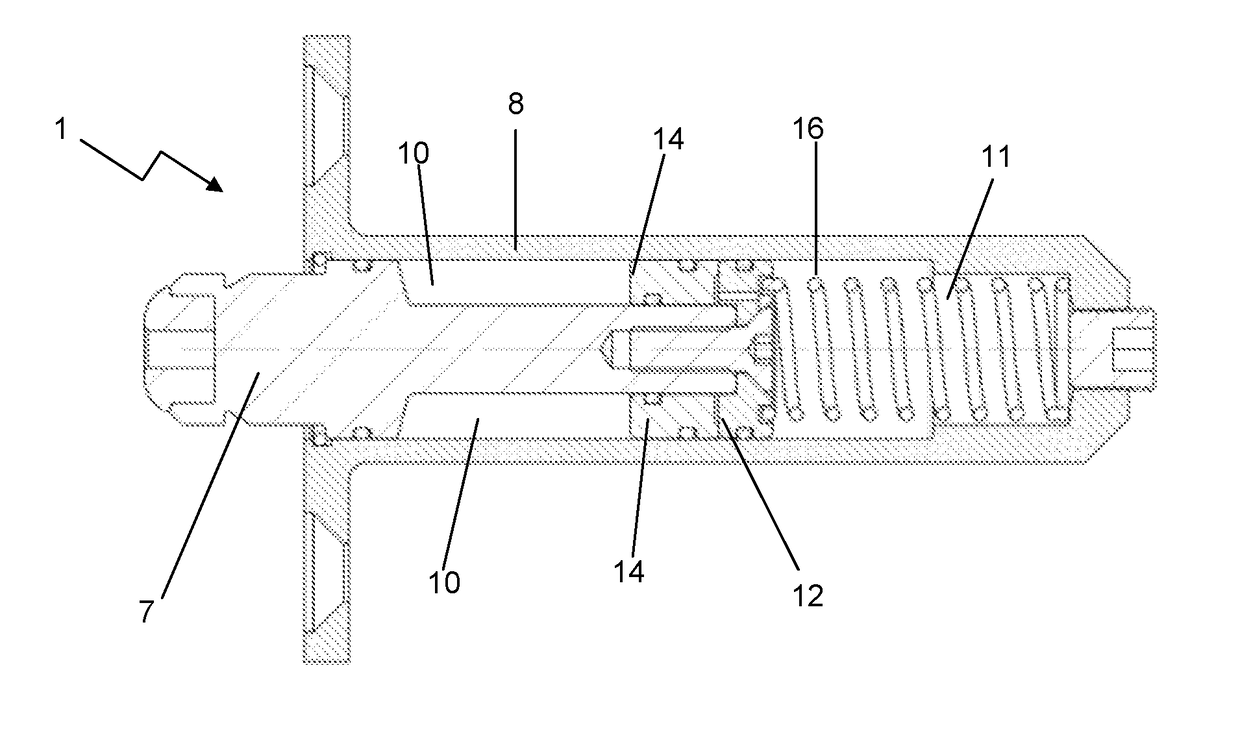
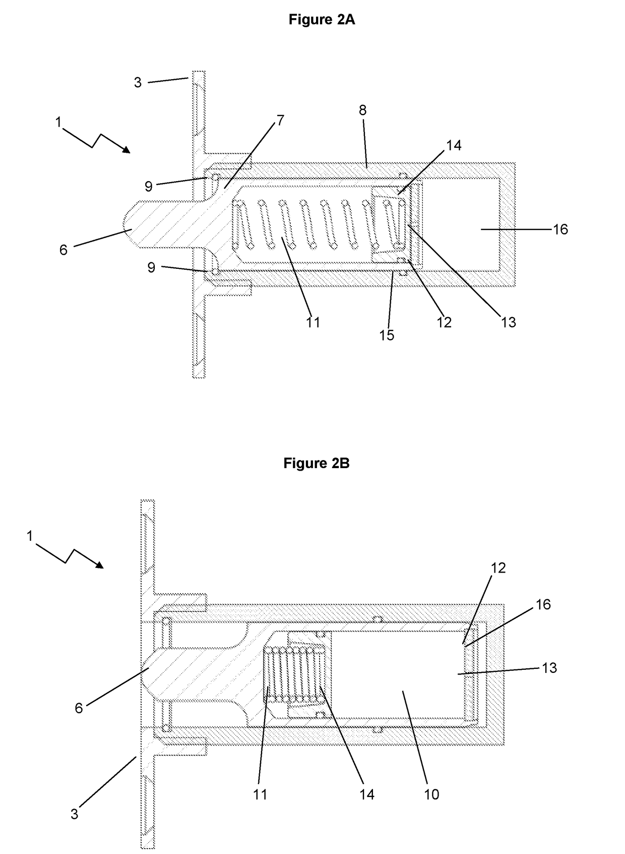
[0176]FIGS. 2A and B illustrates the device according the Embodiment 1 of the present invention.

[0177]The device (1) includes a plunger (7) which is configured to slidably move in the chamber (8) which is also cylindrically shaped. The entrance (5) includes a stop (9). The tip (6) of the plunger (7) protrudes out of the entrance (5) by 18 mm.

[0178]The plunger (7) includes the second cavity (10) and biasing means configured as a spring loaded coil (11). The second cavity (10) is formed by the internal walls of the plunger (7), a partition (12) including the orifice (13), and a movable wall (14) which is engaged with the spring loaded coil (11). The plunger (7) and walls of the chamber (8) include O-rings (15) to effectively seal different parts of the device (1).

[0179]The chamber (8) includes a first cavity (16) which is expanded when the device is in the expanded configuration, as depicted in FIG. 2A. In this configuration, the second cavity (10) is contracted. Moving to FIG. 2B, th...

example 2

[0182]FIGS. 5A and B illustrate the device according the Embodiment 2 of the present invention in an expanded configuration and compacted configuration, respectively.

[0183]In Embodiment 2, the second cavity (10) is formed from an interworking relationship between the plunger (7) configured as a centralized column, the inner walls of the chamber (8), the partition (12) including the orifice (13) and a movable wall (14) which slides about the centralized plunger (7) and against the inner walls of the chamber (8).

[0184]The biasing means (11) is in the first cavity (16) and is biased towards the first cavity (16) being expanded. The first cavity (16) is located in the peripheral portion of the chamber (8) distal to the entrance (5).

[0185]As the plunger (7) is forced into the chamber (8), the material (not shown) transfers through the orifice (13), driving back the movable wall (14) to expand the size of the second cavity (10) to accommodate the displaced material from the first cavity (...

example 3

[0186]FIGS. 6A and B illustrate the device according the Embodiment 3 of the present invention in an expanded configuration and compacted configuration, respectively.

[0187]In Embodiment 3, the partition (12) is a fixed wall integrally built into the chamber (8), with the partition (12) including the orifice (13) including a nozzle (20).

[0188]The second cavity (10) is located on the opposite side to the partition (12) and away from the entrance (5). The second cavity (10) is defined by the inner walls of the chamber (8), the partition (12) and a movable wall (14) biased towards the partition (12) by the spring loaded coil (11).

[0189]The first cavity (16) is located on the opposite side of the partition (12) to the second cavity (10) and nearer to the entrance (5), and is defined by the inner walls of the chamber (8), the partition (12) housing the orifice (13) and by the front surface (21) of the plunger (7).

[0190]The plunger (7) is a solid cylindrical component that drives into the ...


PUM


Abstract

A door anti-slamming device, wherein the device includes a chamber with an entrance located at a first end; wherein the chamber houses a plunger component with a tip configured to slidably move in and out of the entrance, therefore defining a compacted configuration and an extended configuration of the device, respectively; wherein the device includes an biasing means configured to bias the device towards the extended configuration; wherein the device includes a first cavity and a second cavity located within the chamber and / or plunger component, and wherein a partition is located between the first and second cavity characterised in that the partition includes an orifice configured to control material transfer rate between the first cavity and second cavity, wherein the device is configured to transition to the compacted configuration at a rate controlled by the material transfer from the first cavity into the second cavity.

Description

TECHNICAL FIELD[0001]This invention relates to a door anti-slamming device and its method of use.BACKGROUND ART[0002]There is a wide variety of industries and devices that could benefit from door anti-slamming devices. This is from a safety perspective to avoid injury from doors unexpectantly slamming, as well as comfort perspective and avoidance of damage to doors or the surrounding structures.[0003]For example, shipping container doors are very heavy and large. At sea, or even at port, wind can catch a door and quickly cause it to slam against the container walls or entrance, even if a person or safety mechanism is intended to temporarily hold it in place. This may be particularly applicable during inspection of the containers during customs duty which often occurs at sea, or at the time of loading or unloading. If a person is inadvertently in the path of the door as it slams against a surface, the person could be severely injured.[0004]The same applies to other situations, one be...

Claims


Application Information

Patent Timeline
IPC IPC(8): E05F5/02
CPCE05F5/02E05F5/08E05F5/10
Inventor HOPKINS, NICOLAS LEITH
Owner HOPKINS NICOLAS LEITH
Why Eureka
Try Eureka