

Measuring device, measuring method, and programs therefor
a technology of measuring device and measuring method, applied in the field of measuring electromagnetic waves, can solve the problems of complicated operations for identifying the measurement planned position, and achieve the effect of simple and easy method
- Summary
- Abstract
- Description
- Claims
- Application Information
AI Technical Summary
Benefits of technology
Problems solved by technology
Method used
Image

Examples
first embodiment
1. First Embodiment
Outline
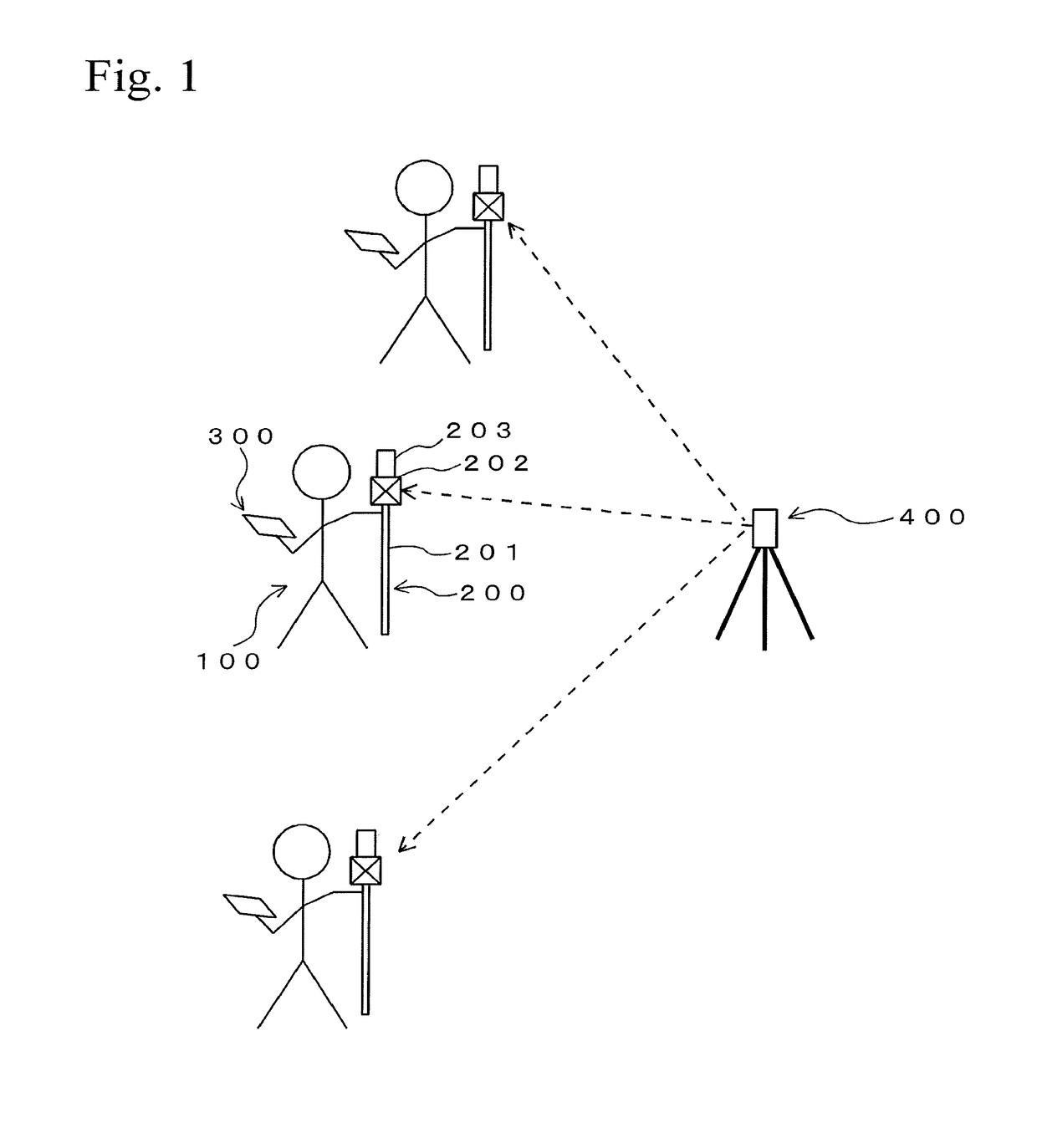
[0027]FIG. 1 shows an outline of work for measuring illuminance in an embodiment. In this embodiment, an operator 100 measures illuminance at a predetermined measurement planned position by using a measuring unit 200. FIG. 1 conceptually shows an example of a case in which the operator 100 moves carrying the measuring unit 200 and a terminal 300 for measuring at three points.
Structure of Hardware
(1) Measuring Unit
[0028]The measuring unit 200 includes a rod-like support pole 201, a reflective prism 202 that is fixed on a top of the support pole 201, and an illuminometer 203 that is fixed on the reflective prism 202. The support pole 201 is extendable, and the operator can adjust the heights of the reflective prism 202 and the illuminometer 203 to desired positions. The support pole 201 can be extended and retracted by a structure that is manually operated by the operator. Alternatively, the extending and the retracting of the support pole 201 may be performe...
example of processing
[0053]FIG. 5 shows a flow chart of an example of a processing procedure. Programs for executing the processing shown in FIG. 5 are stored in a memory of the terminal 300. Alternatively, the programs may be stored in an appropriate storage medium and may be provided therefrom. This is the same as in the case of processing shown in FIG. 7 or FIG. 9.
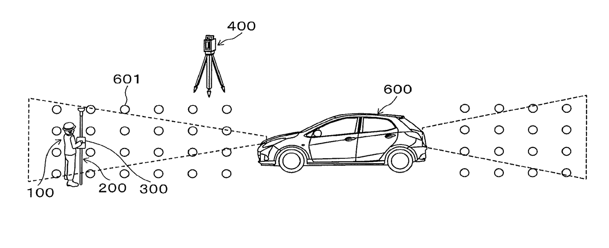
[0054]Here, an example of measuring illuminance of lights (headlights and taillights) of a vehicle 600 will be described. FIGS. 6A and 6B show a condition in which multiple measurement planned positions 601 are set in a grid in a three-dimensional space at a front side and a rear side of the vehicle 600. Although a passenger car is exemplified as a vehicle, a track, a bus, or a special vehicle such as a crane vehicle or the like, may be used.
[0055]Relative positional relationships of the measurement planned positions 601 shown in FIGS. 6A and 6B with respect to the vehicle 600, and grid spaces between the measurement planned positions, are ...
second embodiment
2. Second Embodiment
Outline
[0066]This embodiment relates to a technique for obtaining position data of the position measuring device 400 in the First Embodiment. In the First Embodiment, first, the position of the position measuring device 400 in the measurement field must be determined and be obtained. If the arranged position of the position measuring device 400 is preliminarily determined, the work can be performed according to the method described in the First Embodiment. Otherwise, operations for positioning the position measuring device 400 are necessary. The method described in the Second Embodiment reduces the burden of positioning the position measuring device 400 in such a case.
Structure
[0067]In this embodiment, a terminal 310 shown in FIG. 8 is used instead of the terminal 300 shown in FIG. 3. The terminal 310 is constructed by adding a point cloud position data obtaining unit 311, a three-dimensional model generating unit 312, a three-dimensional model matching unit 313,...
PUM
 Abstract
Description
Claims
Application Information