
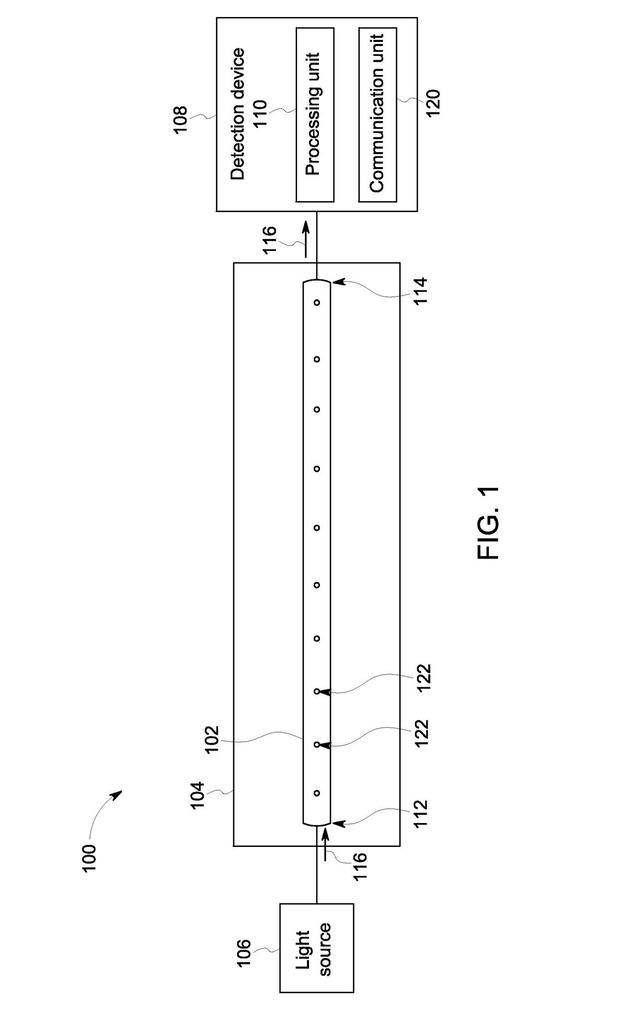
Microstructured optical fibers for gas sensing systems

Inactive Publication Date: 2017-04-06
BAKER HUGHES OILFIELD OPERATIONS LLC
View PDF7 Cites 32 Cited by
  • Summary
  • Abstract
  • Description
  • Claims
  • Application Information

AI Technical Summary

Benefits of technology

The patent describes a microstructured optical fiber (MOF) that includes a cladding with an inner porous microstructure that surrounds a hollow core. The MOF has port holes that allow gas to enter the hollow core and interact with the light energy within it. The MOF can be used as a gas sensing system, where the light energy is coupled into the hollow core and the gas can be detected by analyzing the light that is reflected or transmitted through the gas. The technical effect of this patent is to provide a novel and effective way to detect and analyze gas in a compact and efficient way.

Problems solved by technology

Gases are relatively transparent, however, so the absorption line strength of a gas may be relatively small and hard to detect.
For example, a light source of the spectroscopic sensor may be separated from a detector of the spectroscopic sensor by a distance of one kilometer or more to achieve a necessary path length, but such distances are not practical in most applications.
While this technique allows for a manageable device size, it is problematic due to the need to maintain very exacting alignment of the mirrors.
Variations in conditions, such as temperature changes, vibration, humidity, or the like, may misalign the mirrors or otherwise interfere with the sensitivity and / or accuracy of these optical cavity sensors.
Therefore, this technique is generally not used for remote, unattended measurements in various field environments, such as an oil or gas well pad, a pipeline, a mine, or the like.
Moreover, optical cavity sensors are generally quite expensive.

Method used


Image

  • Microstructured optical fibers for gas sensing systems
  • Microstructured optical fibers for gas sensing systems
  • Microstructured optical fibers for gas sensing systems

Examples


Embodiment Construction

[0022]Various embodiments will be better understood when read in conjunction with the appended drawings. To the extent that the figures illustrate diagrams of the functional blocks of various embodiments, the functional blocks are not necessarily indicative of the division between hardware (including circuitry). Thus, for example, one or more of the functional blocks (e.g., processors, controllers or memories) may be implemented in a single piece of hardware (e.g., a general purpose signal processor or random access memory, hard disk, or the like) or multiple pieces of hardware. Similarly, any programs may be stand-alone programs, may be incorporated as subroutines in an operating system, may be functions in an installed software package, and the like. It should be understood that the various embodiments are not limited to the arrangements and instrumentality shown in the drawings.

[0023]As used herein, the terms “system,”“unit,” or “device” may include a hardware and / or software sys...


PUM


Abstract

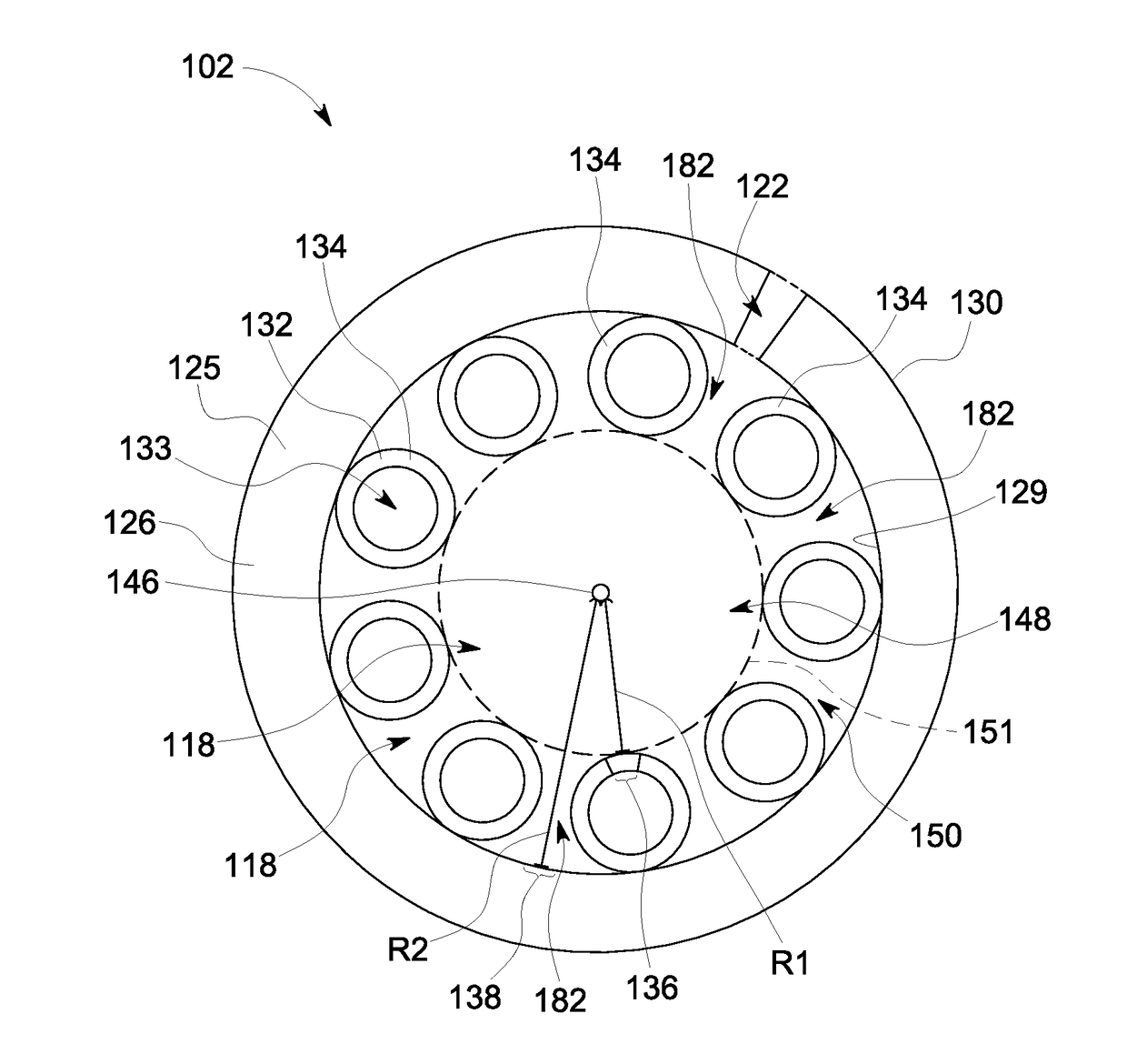
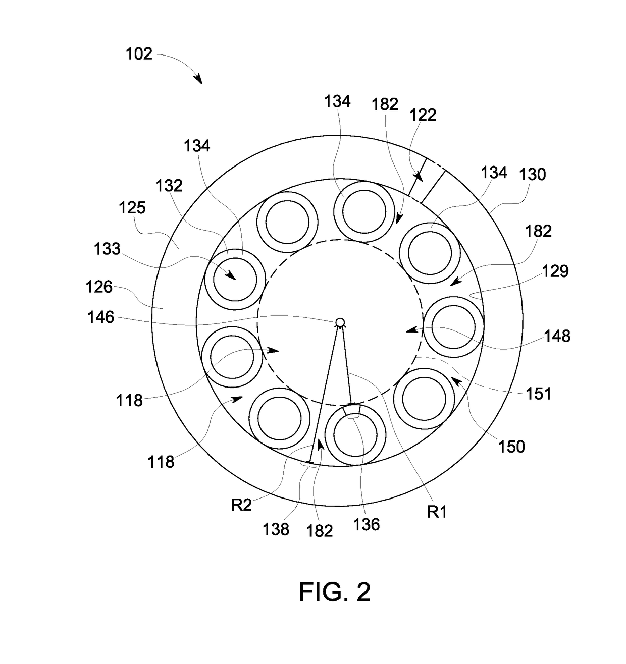
Microstructured optical fiber (MOF) includes a cladding extending a length between first and second ends. The cladding includes an inner porous microstructure that at least partially surrounds a hollow core. A perimeter contour of the hollow core has a non-uniform radial distance from a center axis of the cladding such that first segments of the cladding along the perimeter contour have a shorter radial distance from the center axis relative to second segments of the cladding along the perimeter contour. The cladding receives and propagates light energy through the hollow core, and the inner porous microstructure substantially confines the light energy within the hollow core. The cladding defines at least one port hole that extends radially from an exterior surface of the cladding to the hollow core. Each port hole penetrates the perimeter contour of the hollow core through one of the second segments of the cladding.

Description

GOVERNMENT LICENSE RIGHTS[0001]This invention was made with government support under T-108180 awarded by the Department of Energy. The government has certain rights in the invention.BACKGROUND[0002]Various devices have been developed for sensing and measuring the concentrations of different gases at man-made or natural locations, such as oil wells, pipelines, mines, manufacturing plants, refineries, and the like. Monitoring for the presence and concentration of gases may be used for various applications, such as to ensure that toxic gases (CO, H2S, etc.) are not present in significant concentrations, to ensure that explosive gases (CH4, H2, etc.) are below respective explosive limits, to identify the gases in a mixture (for custody transfer, heat content, etc.), or for various other reasons. Spectroscopy may be used to provide highly sensitive and selective sensors because each gas exhibits a unique spectroscopic fingerprint, such that gases absorb and emit light energy at specific ...

Claims


Application Information

Patent Timeline
IPC IPC(8): G02B6/02G01J3/02G01N21/3504
CPCG02B6/02366G02B6/02309G02B6/02371G01J3/0218G02B6/02347G01N21/3504G01J3/0221G01J3/42G01N21/0303G01N2201/08G02B6/02328G02B6/02338G02B6/024G01N2201/088
Inventor CHALLENER, WILLIAM ALBERTCHOUDHURY, NILOYPALIT, SABARNI
Owner BAKER HUGHES OILFIELD OPERATIONS LLC
Learn More