Unified power flow controller for double-circuit line

a technology of power flow controller and double-circuit line, which is applied in the direction of ac network voltage adjustment, information technology support system, climate sustainability, etc., can solve the problems of poor control effect, occupied space is larger, and investment cost is higher, and achieves excellent economic benefits, flexibility and reliability.

Active Publication Date: 2017-04-06
NR ELECTRIC CO LTD +1
View PDF8 Cites 12 Cited by
  • Summary
  • Abstract
  • Description
  • Claims
  • Application Information

AI Technical Summary

Benefits of technology

[0006]An objective of the present invention is to provide a UPFC suitable for a double-circuit power transmission line, this topological structure can realize various operation modes, when one current converter is in fault, power flow control of the double-circuit transmission line can still be achieved, one parallel-connection side converter can be saved, and the UUPFC is excellent in economy, flexibility and reliability.

Problems solved by technology

Since the power transmission networks in China are mostly double-circuit or multi-circuit line, the power flow optimization problem and N−1 overcurrent problem occur in the multi-circuit line, and if only one circuit of the multi-circuit line is provided with the UPFC to control the power flow of the line, a control effect is poor.
If a set of whole UPFC is mounted on each circuit of the double-circuit line, each UPFC consists of a static synchronous compensator (comprising a parallel-connection transformer and a parallel-connection side converter) and a static synchronous series-connection compensator (comprising a series-connection transformer and a series-connection side converter) which are connected, and four converters and four transformers are required in total, the occupied space is larger and the investment cost is higher; and when any converter is failed, the power flow control over the double-circuit power transmission line is not realized.

Method used


Image

  • Unified power flow controller for double-circuit line
  • Unified power flow controller for double-circuit line
  • Unified power flow controller for double-circuit line

Examples


Embodiment Construction

[0028]Embodiments of the present invention are explained in detail in combination with the drawings.

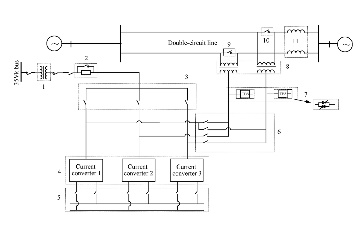
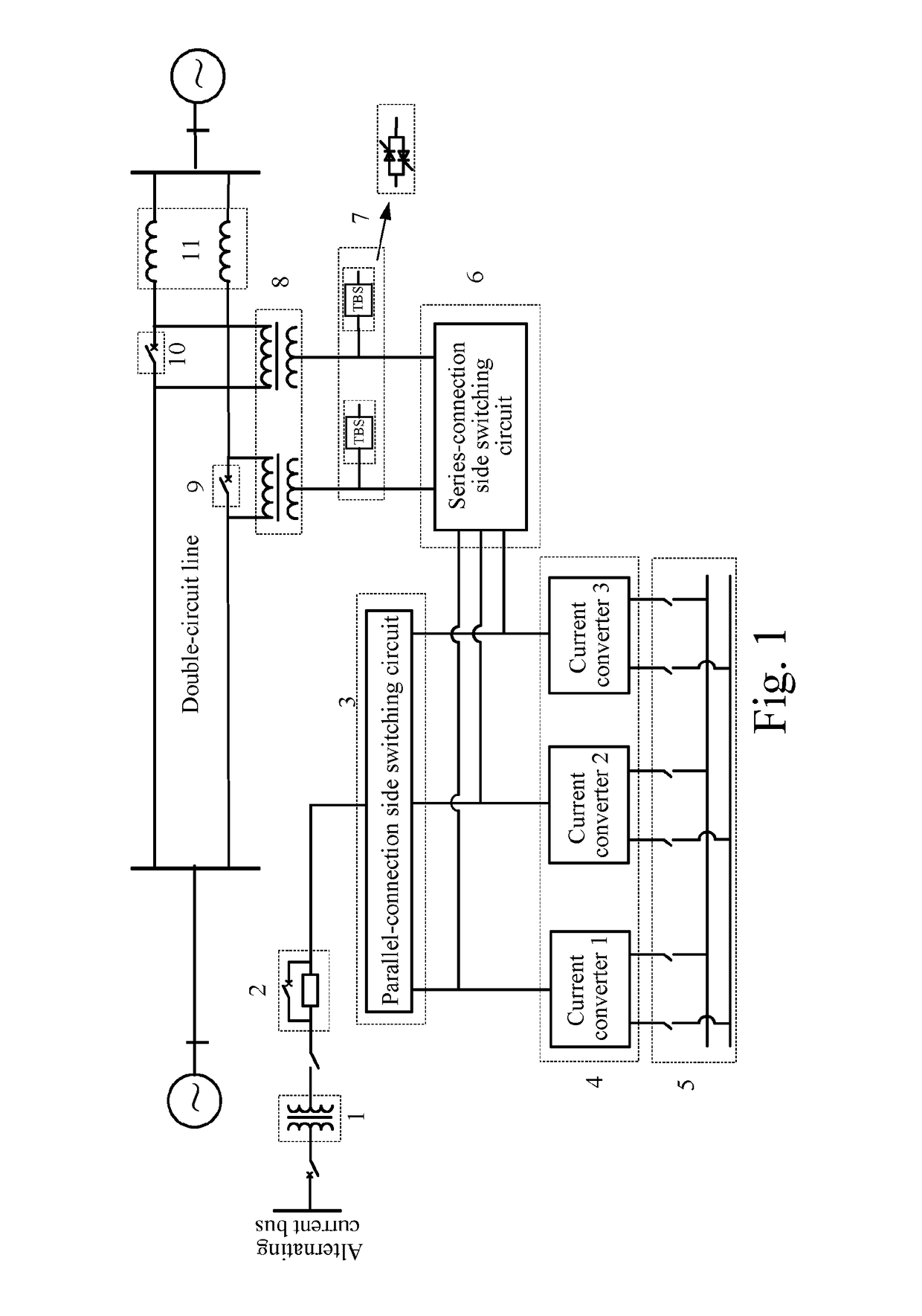
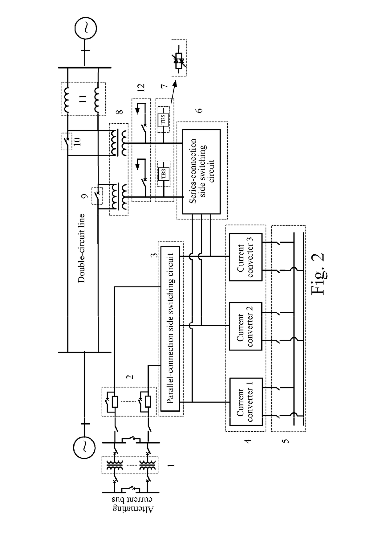
[0029]The present invention provides a UPFC suitable for a double-circuit transmission line, and one of its preferable embodiments is as shown in FIG. 1, in which, 1 is a parallel-connection transformer, 2 is a parallel-connection side starting circuit, 3 is a parallel-connection switching circuit, 4 is a voltage source converter, 5 is a direct current bus and a change-over switch, 6 is a series-connection switching circuit, 7 is a parallel-connection fast by-pass switch of a valve side winding of the series-connection transformer, 8 is a series-connection transformer, 9 and 10 are parallel-connection by-pass circuit breakers of a line side winding of the series-connection transformer and 11 is a reactance of a double-circuit line value.

[0030]The UPFC comprises at least one parallel-connection transformer 1, a starting circuit 2, three current converters 4, at least two series-connect...


PUM


Abstract

A unified power flow controller for a double-circuit transmission line comprises at least one parallel-connection transformer, three current converters, at least two series-connection transformers, a parallel-connection side switching circuit, a series-connection side switching circuit and a direct current common bus. The series-connection transformers connected with at least one group of by-pass switches in parallel. The three current converters connected to each loop line in series after being connected with at least one series-connection transformer through the series-connection side switching circuit. The three current converters connected to an alternating current system after connected with at least one parallel-connection transformer through a parallel-connection side switching circuit starting circuit. The three current converters are connected to the direct current common bus through a transfer switch.

Description

FIELD OF THE INVENTION[0001]The present invention relates to a flexible alternating current power transmission technology, in particular to a unified power flow controller for a double-circuit line.BACKGROUND[0002]Along with interconnection of large-sized power systems and various new devices, the scale and complexity of the power system are increased while power generation and power transmission are more economic and efficient; in addition, since massive distributed power generation systems are connected to a power grid, the traditional fixed power flow transmitted to a power distribution network from a power transmission network is reversed; the continuous increase of user loads needs a power flow control means to improve the existing power transmission capacity; and the power exchange between the flourish smart power grid and the power market needs frequent power flow control.[0003]A unified power flow controller (UPFC) is the power flow control device having the best universalit...

Claims


Application Information

Patent Timeline
Patent Type & Authority Applications(United States)
IPC IPC(8): H02J3/14H02J3/46H02J3/16
CPCH02J3/14H02J3/46H02J3/16H02J3/1814Y02E40/10Y04S20/222Y02B70/3225
Inventor TIAN, JIELI, HAIYINGWANG, XINBAODONG, YUNLONGSHEN, QUANRONGPAN, LEILIU, CHAOCHANG, BAOLI
Owner NR ELECTRIC CO LTD
Why Eureka
Try Eureka