Single Reservoir Beverage Maker

a beverage maker and single reservoir technology, applied in beverage vessels, domestic applications, kitchen equipment, etc., can solve the problems of lukewarm beverage and at least initial absorption of the reservoir

Inactive Publication Date: 2017-04-13
HAMILTON BEACH BRANDS
View PDF8 Cites 9 Cited by
  • Summary
  • Abstract
  • Description
  • Claims
  • Application Information

AI Technical Summary

Benefits of technology

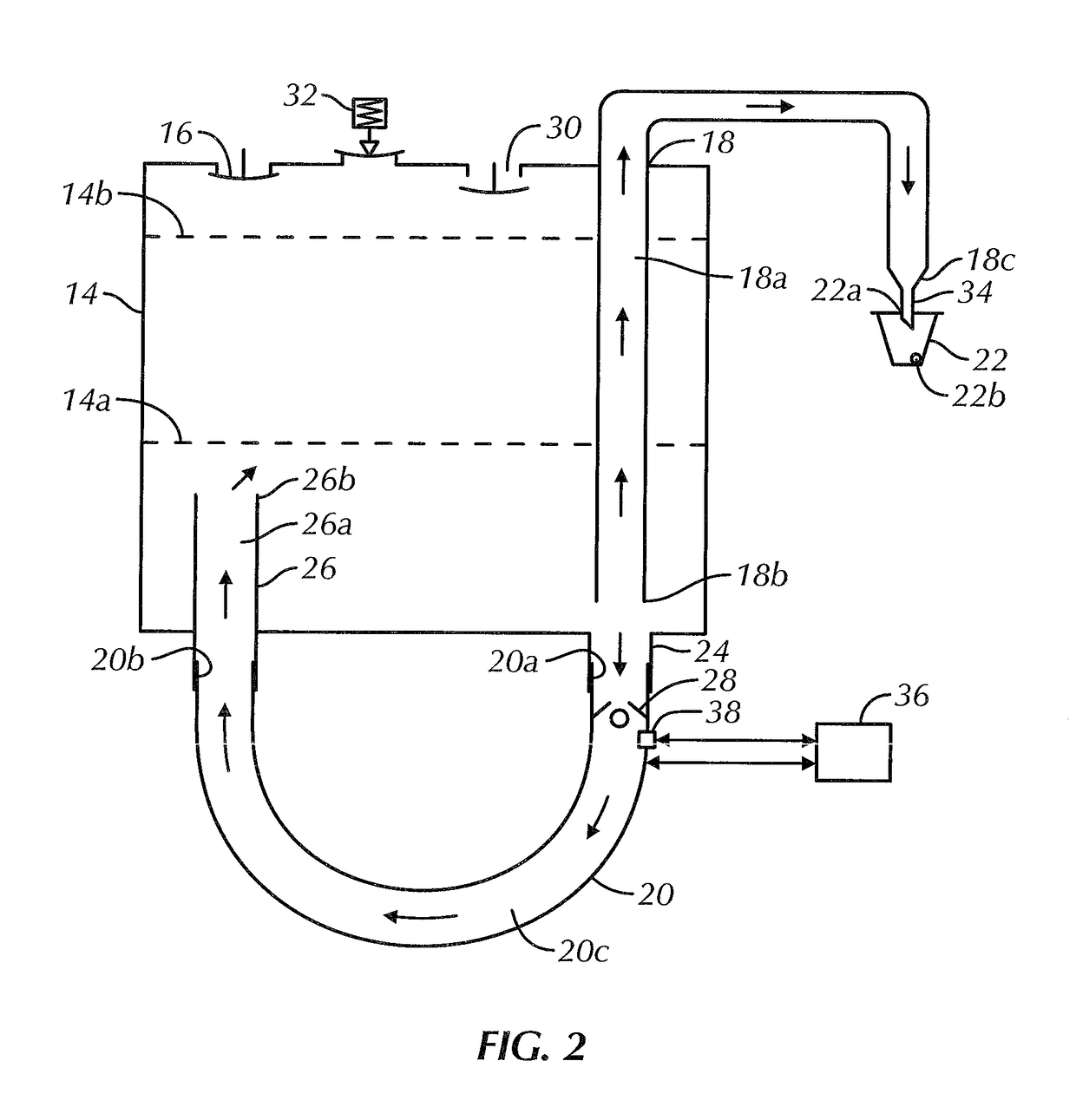
[0009]A vent valve is in fluid communication with the reservoir, the vent valve being biased open, permitting gas flow therethrough, and configured to close when gas exiting the reservoir through the vent valve reaches a threshold flow rate. A pressure relief valve is in fluid communication with the reservoir and is biased closed, and is configured to open when pressure within the reservoir reaches a predetermined value. Liquid within the reservoir flows into the HLG passageway via the reservoir second outlet port and the HLG inlet, and powering of the HLG increases a temperature of at least a portion of the liquid within the HLG passageway and effectuates movement of the liquid in the HLG passageway back to the reservoir via the HLG outlet and the reservoir second inlet port. Liquid is continuously recirculated between the reservoir and the HLG, without exiting from the reservoir first outlet port, at least until the vent valve is closed.
[0010]Yet another aspect of the present disclosure is directed to a beverage maker comprising a reservoir having a first inlet port for receiving a volume of liquid to be used for preparing a beverage and a first outlet port for discharging the liquid from the reservoir to a brew chamber to prepare the beverage. A hot liquid generator (HLG) having an HLG inlet is in fluid communication with a second outlet port of the reservoir and an HLG outlet is in fluid communication with a second inlet port of the reservoir and a passageway extends therebetween. A valve is in fluid communication with the reservoir and is normally in an open position, permitting gas flow therethrough. The valve is moveable into a closed position, preventing gas flow therethrough.
[0011]Liquid within the reservoir flows into the HLG passageway via the reservoir second outlet port and the HLG inlet, and powering of the HLG increases a temperature of at least a portion of the liquid within the HLG passageway and effectuates movement of the liquid in the HLG passageway back to the reservoir via the HLG outlet and the reservoir second inlet port. Liquid is continuously recirculated between the reservoir and the HLG, without exiting from the reservoir first outlet port, at least until the valve is closed.

Problems solved by technology

One drawback of the liquid residing in the dispensing reservoir is that the dispensing reservoir may at least initially absorb heat from the heated liquid.
The affect of such cooling of an initial volume of the liquid is exacerbated when the desired beverage is of a smaller serving size, i.e., resulting in a lukewarm beverage.

Method used


Image

  • Single Reservoir Beverage Maker
  • Single Reservoir Beverage Maker
  • Single Reservoir Beverage Maker

Examples


Embodiment Construction

[0020]Certain terminology is used in the following description for convenience only and is not limiting. The words “lower,”“bottom,”“upper” and “top” designate directions in the drawings to which reference is made. The words “inwardly,”“outwardly,”“upwardly” and “downwardly” refer to directions toward and away from, respectively, the geometric center of the beverage maker, and designated parts thereof, in accordance with the present disclosure. Unless specifically set forth herein, the terms “a,”“an” and “the” are not limited to one element, but instead should be read as meaning “at least one.” The terminology includes the words noted above, derivatives thereof and words of similar import.

[0021]It should also be understood that the terms “about,”“approximately,”“generally,”“substantially” and like terms, used herein when referring to a dimension or characteristic of a component of the disclosure, indicate that the described dimension / characteristic is not a strict boundary or parame...


PUM


Abstract

A beverage maker includes a reservoir having a first inlet port for receiving liquid for preparing a beverage and a first outlet port for discharging the liquid from the reservoir to a brew chamber. A hot liquid generator (HLG) inlet is in fluid communication with a reservoir second outlet port and an HLG outlet is in fluid communication with a reservoir second inlet. A valve fluidly communicates with the reservoir, the valve being normally in an open position, permitting flow therethrough, and moveable into a closed position, preventing flow therethrough. Liquid flows into the HLG via the reservoir second outlet. HLG powering increases the temperature of the liquid therein and effectuates movement of the liquid back to the reservoir via the HLG outlet. Liquid is continuously recirculated between the reservoir and the HLG, without exiting from the reservoir first outlet port, at least until the valve is closed.

Description

CROSS REFERENCE TO RELATED APPLICATIONS[0001]This application claims priority to U.S. Provisional Patent Application No. 62 / 238,484, filed on Oct. 7, 2015, entitled “Single Vessel Beverage Maker,” and U.S. Provisional Patent Application No. 62 / 278,744, filed on Jan. 14, 2016, entitled “Single Reservoir Beverage Maker,” the entire contents of each of which are incorporated by reference herein.BACKGROUND OF THE DISCLOSURE[0002]The present disclosure is generally directed to a beverage maker, and more particularly, to a steam operated single reservoir beverage maker.[0003]Some hot beverage, single-serve makers, whether steam or pump operated, employ a two reservoir system. The receiving reservoir receives a volume of liquid at room temperature. The liquid exits the receiving reservoir, is gradually heated in a heater and thereafter enters into a dispensing reservoir where the liquid resides until dispensing thereof through foodstuff grounds for brewing the beverage.[0004]One drawback o...

Claims


Application Information

Patent Timeline
Patent Type & Authority Applications(United States)
IPC IPC(8): A47J31/56A47J31/46
CPCA47J31/465A47J31/56
Inventor HANES, ADAMMULVANEY, PATRICK T
Owner HAMILTON BEACH BRANDS
Why Eureka
Try Eureka