Network Traffic-Compatible Time Domain Reflectometer

a network traffic and reflectometer technology, applied in the direction of digital transmission, time-division optical multiplex system, transmission path sub-channel allocation, etc., can solve the problem of difficult tdr employment inability to test tdr in live hfc network, and inability to detect mismatches. to achieve the effect of wide bandwidth and maximize time resolution and accuracy

Active Publication Date: 2017-04-13
ARCOM DIGITAL
View PDF2 Cites 64 Cited by
  • Summary
  • Abstract
  • Description
  • Claims
  • Application Information

AI Technical Summary

Benefits of technology

[0017]It is still a further object of the present invention to provide TDR apparatus and methods that calibrate a level of a probe signal to be injected into a HFC network under test, where the calibrated level minimizes the chance that the probe signal will interfere with the service signals of the network.
[0018]It is yet another object of the present invention to provide TDR apparatus and methods that utilize a probe signal having a relatively wide bandwidth to maximize the time resolution and accuracy of pinpointing the location of an impairment in a coaxia

Problems solved by technology

Detection and location of mismatches can be a challenging problem in an HFC network carrying signal traffic or service signals (“live HFC network”).
Employment of TDR in a live HFC network is challenging because of the number of service signals present and the fact that the service signals can be disrupted by the probe signal and can interfere with the detection of reflected probe signals (e.g., a low-level reflected probe signal can be masked by strong service signals).
Thus, heretofore, TDR has not been very practicable for testing in a live HFC network.
This is not as accurate as traditional TDR using a wideband probe signal.
The accuracy of the PNM technique is limited by the bandwidth of one upstream QAM channel (6.4 MHz in the U.S.) and by the number of pre-equalization coefficients.
However, this downstream technique has some drawbacks.
Therefore, to achieve an adequate accumulation time it may be necessary to carry out a large number of captures, which could take time and impact CM signal traffic.
Another limitation is that continuous wave (CW) or narrowband downstream signals, such as analog video carriers, AGC pilots, and OFDM pilot subcarriers, may be included in the autocorrelation, which could contribute flat or spread components to the function.
These flat or spread components could mask actual reflection spikes and reduce sensitivity and time resolution (distance accuracy).
However, in a modern HFC network, the capturing and processing of the full-spectrum

Method used


Image

  • Network Traffic-Compatible Time Domain Reflectometer
  • Network Traffic-Compatible Time Domain Reflectometer
  • Network Traffic-Compatible Time Domain Reflectometer

Examples


Embodiment Construction

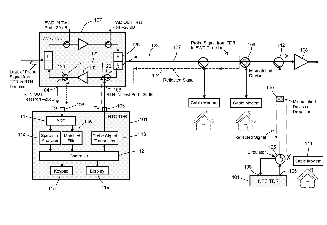
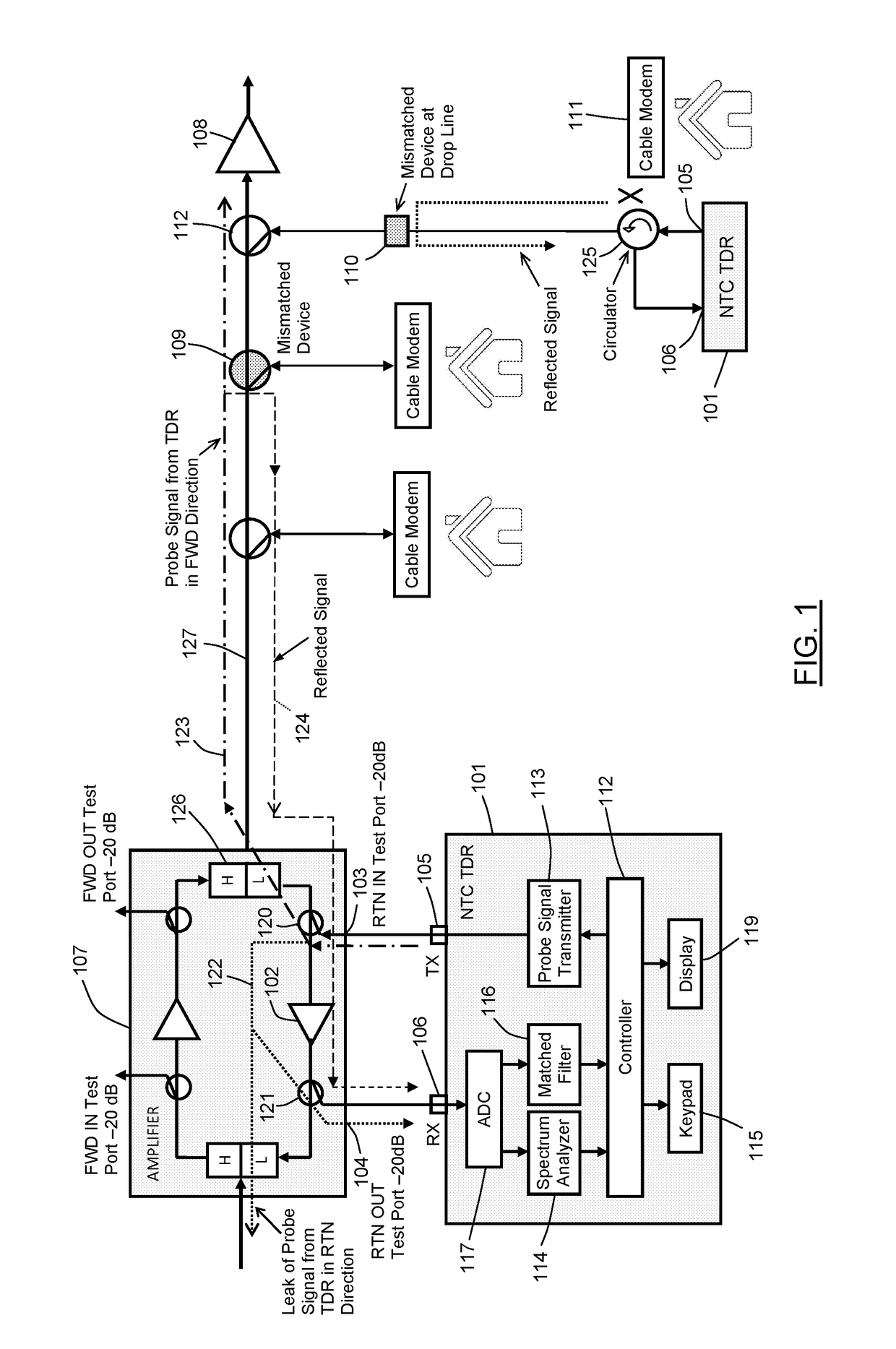
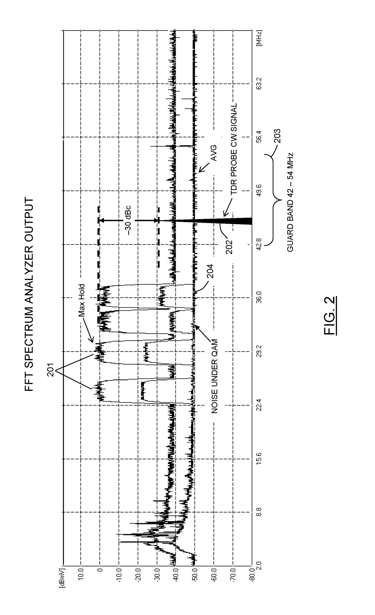
[0042]Time domain reflectometry (TDR) apparatus and methods according to the preferred embodiment of the present invention is based on the following features:[0043]1. Using low-level spread spectrum probe signals within full upstream bandwidth of an HFC network, to prevent interference with service signals and provide maximum time resolution;[0044]2. Injection of a continuous wave (CW) calibration or test signal into the guard band, between upstream and downstream bands, before testing network with probe signal, for accurate setting of probe signal level (operational level) to prevent interference with upstream service signals;[0045]3. Using coherent sequence of short chirp pulses, as the preferred spread spectrum probe signal, for providing immunity from high-level QAM burst signals in upstream band and further reducing interference with the QAM and other service signals; and[0046]4. Receiving reflected probe signal in time intervals when there are no high-level QAM burst signals, ...


PUM


Abstract

A TDR for locating impairments in an HFC network is claimed. The network carries burst signals in an upstream band during burst intervals. The TDR comprises a transmitter, receiver, level detector, controller, accumulator, and probe detector. The transmitter transmits probe signals to the impairment, causing a reflection of the probe signals. Each probe signal is in the upstream band and has a bandwidth extending the width of the upstream band. The receiver receives the reflected probe signals during receiving intervals, and receives the burst signals during receiving intervals that overlap burst intervals. The level detector measures a level of the signals received during each receiving interval. The controller determines which of the receiving intervals are free of burst signals, based on the level measurement. The accumulator accumulates reflected probe signals received during intervals free of burst signals. The probe detector detects the impairment from the accumulated probe signals and estimates a time delay for the impairment. A distance to the impairment is estimated from the time delay.

Description

CROSS-REFERENCE TO RELATED APPLICATIONS[0001]This application claims the benefit of U.S. Provisional Application No. 62 / 240,492, filed Oct. 12, 2015, which is incorporated herein by reference.BACKGROUND OF THE INVENTION[0002]Field of Invention[0003]The present invention relates generally to monitoring impairments in a Hybrid Fiber-Coax (HFC) network, and more particularly to apparatus and methods for detecting and locating linear impairments such as, but not limited to, impedance mismatches causing micro-reflections in a coaxial cable plant of an HFC network.[0004]Background Art[0005]Micro-reflections are one of the most critical impairments in an HFC network, especially in the return path where signal losses in the cable are minimal and reflected signals from even remote impedance mismatches can impact upstream service signals from DOCSIS cable modems (CMs). Detection and location of mismatches can be a challenging problem in an HFC network carrying signal traffic or service signal...

Claims


Application Information

Patent Timeline
IPC IPC(8): H04B10/071H04J14/08H04B10/2575H04L5/00H04B10/079
CPCH04B10/071H04L5/0048H04J14/08H04B10/25751H04B10/0793H04B10/0771
Inventor ZINEVICH, VICTOR M.
Owner ARCOM DIGITAL
Why Eureka
Try Eureka