Method and data processing device for severity assessment of bearing defects using vibration energy

a data processing device and severity assessment technology, applied in the field of condition monitoring of rolling bearings, can solve the problems of affecting industrial implementation, affecting the severity of bearing damage, and fixed quantitative alert and alarm thresholds, etc., and achieve the effect of improving reliability

Active Publication Date: 2017-04-20
AB SKF
View PDF3 Cites 30 Cited by
  • Summary
  • Abstract
  • Description
  • Claims
  • Application Information

AI Technical Summary

Benefits of technology

[0011]The invention seeks to provide a method enabling an automated bearing vibration condition Severity Rating (SR) value based on vibration Acceleration Enveloping (gE) measu...

Problems solved by technology

However many of the advanced or “smart” methods, though impressive from an academic viewpoint, are lacking in cross industry field experience and the complexity results in bars to the industrial implementation.
A problem that affects Condition Monitoring (CM) across all types of machines is at what level Alert and Alarm (Amber and Red) thresholds should be configured for reliable bearing defect detection, in particular when utilizing Acceleration Enveloping measurements.
Any method that utilizes the higher frequency ranges of vibration for quantitative (absolute amplitude) assessment of bearing damage severity is plagued with many factors that can significantly amplify or attenuate the amplitudes observed.
Hence within these higher frequency ranges the use of fixed quantitative Alert and Alarm thresholds across a range of different applications or even similar applications is unworkable, so individual thresholds are necessary which require many man-hours of an analysts time to fine tune these thresholds from sensor ...

Method used


Image

  • Method and data processing device for severity assessment of bearing defects using vibration energy
  • Method and data processing device for severity assessment of bearing defects using vibration energy
  • Method and data processing device for severity assessment of bearing defects using vibration energy

Examples


Embodiment Construction

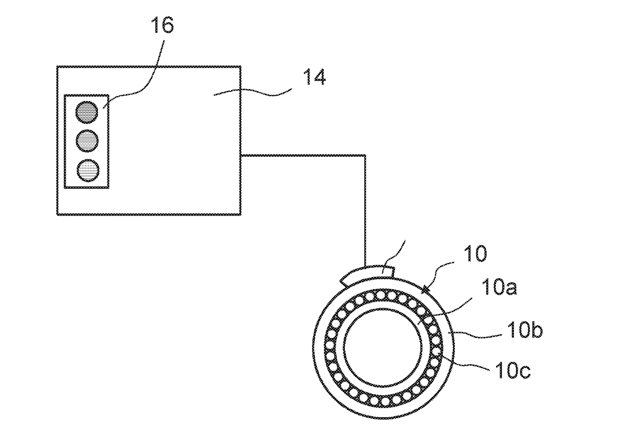
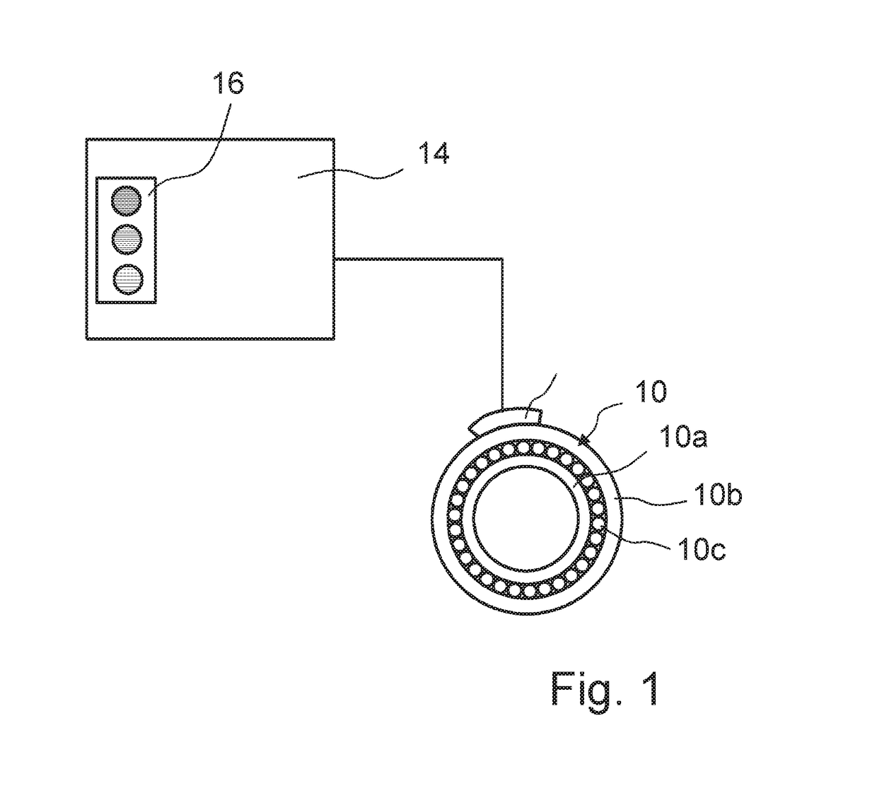
[0092]FIG. 1 is a schematic view of a machine including a bearing 10 having an inner ring 10a and an outer ring 10b and at least one row of rolling elements 10c arranged between the inner ring 10a and the outer ring 10b, wherein the rolling elements 10c roll on the inner raceway of the inner ring 10a and on the outer raceway of the outer ring 10b. The bearing 10 is equipped with an acceleration sensor 12 configured to measure vibrations of the outer ring 10b of the bearing 10.

[0093]The machine is equipped with a condition monitoring system according to the invention, which includes the sensor 12, a data processing device 14 and a signal output device 16 such as a warning lamp or a monitor. The sensor data obtained by the sensor 12 include background noise and a regular, quasi-periodic, frequency- and load-dependent contribution of the passing rolling elements 10c.

[0094]In the embodiment of FIG. 1, the data processing device 14 is connected to the sensor 12 by a wire. However, the s...


PUM


Abstract

Method for detecting bearing defect severity based on bearing rotation speed and at least one data sample of sensor data obtained to measure vibrations of a bearing ring is provided. The method includes converting the data sample from time domain to frequency domain to obtain a signal frequency spectrum; determining a defect center frequency of the bearing using the rotation speed; and identifying a predetermined number of frequency peaks of the signal frequency spectrum. A total vibration energy in an overall frequency band including the predetermined number of frequency peaks is first determined; next, for each of the frequency peaks, a peak energy as a spectral energy of signal components giving rise to the frequency peaks is determined; calculating a bearing defect spectral energy using the peak energies; and finally a ratio of the bearing defect spectral energy and a total vibration energy to assess a defect severity is obtained.

Description

CROSS REFERENCE TO RELATED APPLICATIONS[0001]This application claims priority to British patent application no. 1518545.7 filed on Oct. 20, 2015 , the contents of which are fully incorporated herein by reference.FIELD OF THE INVENTION[0002]The invention relates to the field of condition monitoring in rolling bearings based on acoustic or acceleration measurements.BACKGROUND OF THE INVENTION[0003]It is known to use acceleration and / or vibration sensors attached to bearing rings of rolling bearings to detect defects in the rolling elements or on the raceways. The sensor data are processed either in a data processing unit integrated in the bearing or attached to the bearing or to its housing or alternatively in a remote monitoring unit.[0004]The bearing condition monitoring technology has been originally conceived for large-size bearings for use e.g. in wind turbines or trains. The scope of applicability of the bearing condition monitoring technology now continuously expands toward bea...

Claims


Application Information

Patent Timeline
IPC IPC(8): G01M13/04
CPCG01M13/045F16C19/522F16C19/527G01M13/04G01H1/00G01N29/4463
Inventor THOMSON, ALLAN
Owner AB SKF
Why Eureka
Try Eureka