Computer intelligent imaging-based system for automatic pest identification and pest-catching monitoring

a technology of intelligent imaging and pest detection, applied in the field of intelligent pest detection devices, can solve the problems of large labor and time consumption of current sticking-type pest-catching devices on the market, consuming many unnecessary labor costs, and taking 2 working days, so as to save 1 working day, reduce maintenance and consumable costs, and improve economic benefits.

Inactive Publication Date: 2017-04-27
SHANGHAI XINGRANG IND
View PDF1 Cites 30 Cited by
  • Summary
  • Abstract
  • Description
  • Claims
  • Application Information

AI Technical Summary

Benefits of technology

[0023]The pest conditions are recorded through the imaging lens and the imaging control module in the Invention; the data is transmitted to the cloud data server and the data display module through the data transmission module and further transmitted to the terminal control module and the pest identification module; thus analysis, identification and remote monitoring of the pest species and quantities are realized. The Invention solves the technical defects of current products through the above intelligent imaging system. If using a pest-catchin...

Problems solved by technology

With 5 steps as changing adhering paper, checking and sorting pests, filling in record card, filing records and analyzing pests, the current sticking-type pest-catching device on the market consumes large quantity of labor and time.
Thus, the maintenance cost for pest services in food processing and food related industries stays at a high level.
In total, it takes 2 working days and consumes many unnecessary labor cost.
Moreover, all of these procedures are finished by personnel (such as artificial field maintenance and artificial identification), causing ...

Method used


Image

  • Computer intelligent imaging-based system for automatic pest identification and pest-catching monitoring
  • Computer intelligent imaging-based system for automatic pest identification and pest-catching monitoring
  • Computer intelligent imaging-based system for automatic pest identification and pest-catching monitoring

Examples


embodiment 1

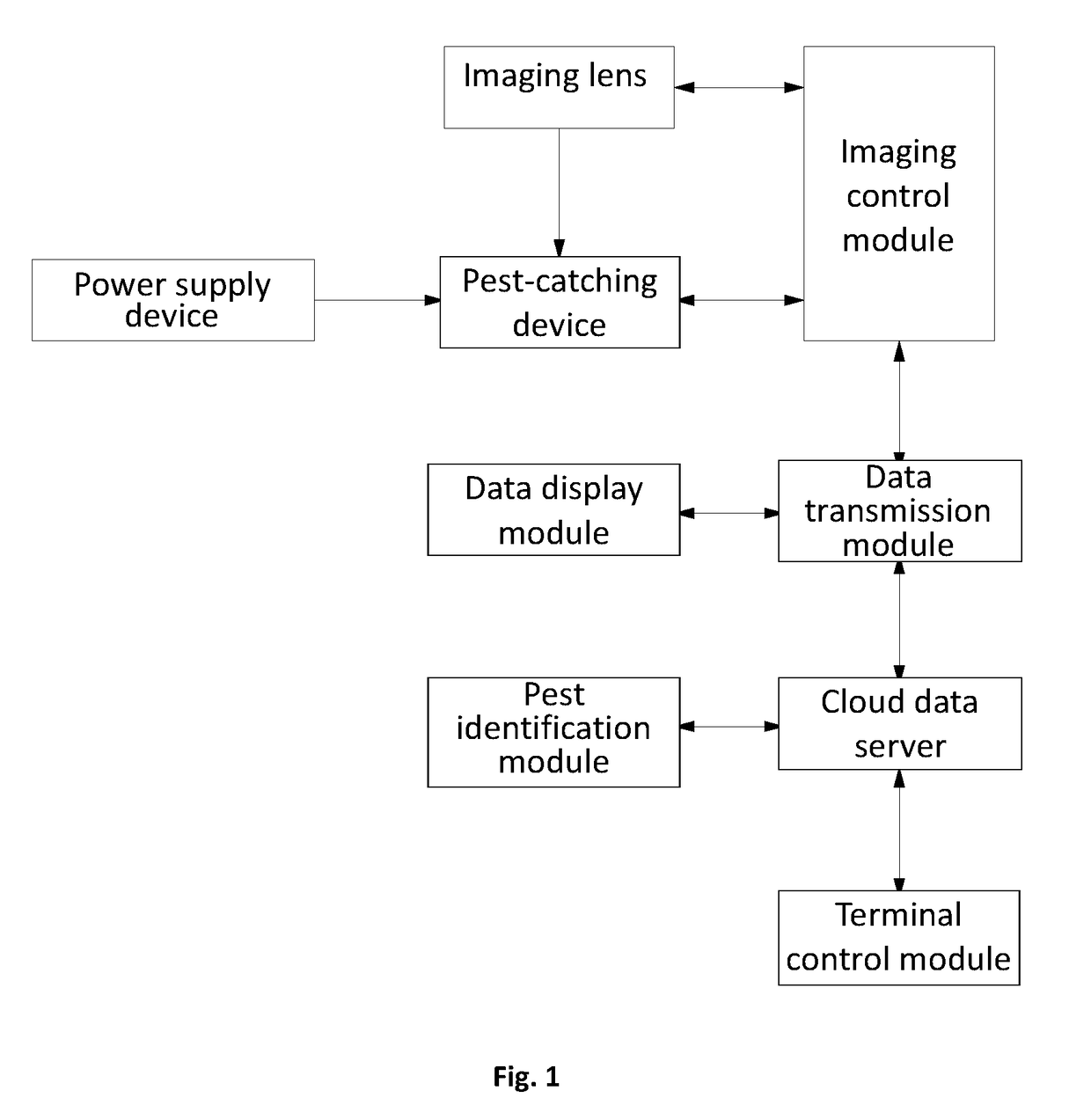
[0040]As shown in FIG. 1, the computer intelligent imaging-based system for automatic pest identification and pest-catching monitoring of the Embodiment comprises a pest-catching device, an imaging lens, an imaging control module, a power supply device, a data transmission module, a cloud data server, a pest identification module, a terminal control module and a data display module.

[0041]The imaging lens and the imaging control module are arranged on the pest-catching device; an intelligent chip is arranged in the imaging control module to mainly control imaging time and effect of the imaging lens, and processing, compressing, storage and transmission of images.

[0042]The imaging lens comprises a video imaging lens, a picture-taking imaging lens and an infrared imaging lens; the video imaging lens makes video, which will be cut into images through processing by the imaging control module and transmitted to the cloud data server; the picture-taking imaging lens takes pictures and tran...

embodiment 2

[0065]The computer intelligent imaging-based system for automatic pest identification and pest-catching monitoring in the Embodiment has the same structure and working principle with those described in Embodiment 1 except for the pest-catching device.

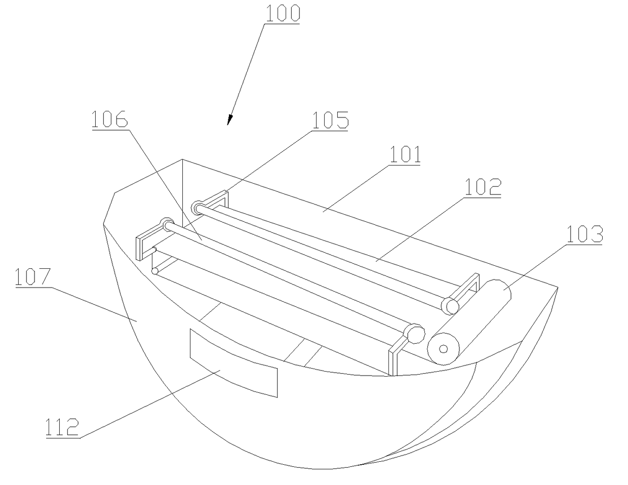
[0066]As shown in FIGS. 6-8, the pest-catching device 200 of the Embodiment comprises a fixed backboard 201, a lamp cover 202 and a glue-storing box 203, a UVA trap lamp 204 and a bracket 205 that are arranged in the lamp cover 202; the UVA trap lamp 204 is arranged on the fixed backboard 201 through the bracket 205 and the glue-storing box 203 is arranged below the UVA trap lamp 204.

[0067]A rolling mechanism is arranged on the glue-storing box 203; the rolling mechanism comprises a conveyor belt 206, a first gear shaft 207, a second gear shaft 208, a third gear shaft 209 and a driving motor 210. The conveyor belt 206 passes through the first gear shaft 207, the second gear shaft 208 and the third gear shaft 209 in sequence and forms a ...

embodiment 3

[0070]The computer intelligent imaging-based system for automatic pest identification and pest-catching monitoring in the Embodiment has the same structure and working principle with those described in Embodiment 1 except for the pest-catching device.

[0071]As shown in FIGS. 9-11, the pest-catching device 300 of the Embodiment comprises a housing 301, an automatic screening mechanism, an automatic cleaning mechanism arranged in the housing 301, and a trap lamp 302 arranged above the housing 301; both sides of the housing 301 are arranged with a fly-suction inlet 303 and a fly-exhaust outlet 304. The automatic cleaning mechanism is arranged below the automatic screening mechanism; a mounting bracket 305 is arranged at the bottom of the housing 301; a transparent self-cleaning explosion-proof lamp cover 306 is arranged outside of the trap lamp 302; a metal protective net 307 is arranged outside of the transparent self-cleaning explosion-proof lamp cover 306.

[0072]An imaging lens 308 an...


PUM


Abstract

A computer intelligent imaging-based system for automatic pest identification and pest-catching monitoring, including a pest-catching device, an imaging lens, an imaging control module, a power supply device, a data transmission module, a cloud data server, a pest identification module, a terminal control module and a data display module; the invention records the pest conditions and transmits the data to the cloud data server and the data display module, and further transmits the data to the terminal control module and the pest identification module to realize analysis, identification and remote monitoring of the species and quantity of the pests. It only takes only 6 minutes for 1 person to finish the works for 100 pest-catching devices and get through the steps of filing records and analyzing pests. Compared with the prior art, it saves 1 day of working time and significantly reduces the costs for maintenance and consumables.

Description

CROSS REFERENCE TO RELATED APPLICATIONS[0001]The present application is a Continuation-In-Part Application of PCT application No. PCT / CN2014 / 087238 filed on Sep. 24, 2014. All the above are hereby incorporated by reference.TECHNICAL FIELD[0002]The invention relates to an intelligent pest-catching device, and particularly to a computer intelligent imaging-based system for automatic pest identification and pest-catching monitoring.BACKGROUND ART[0003]With 5 steps as changing adhering paper, checking and sorting pests, filling in record card, filing records and analyzing pests, the current sticking-type pest-catching device on the market consumes large quantity of labor and time. Thus, the maintenance cost for pest services in food processing and food related industries stays at a high level. For example, it takes 1 day for 1 technician to work on the steps of changing adhering paper, checking and sorting pests and filling in record card and takes 1 day for 1 technician to work on the ...

Claims


Application Information

Patent Timeline
IPC IPC(8): A01M1/14A01M1/08G06K9/00B65G49/02H04N7/18H04N5/33A01K29/00A01M1/10
CPCA01M1/145A01K29/00A01M1/08A01M1/106H04W88/06H04N7/183H04N5/33G06K9/00362H04L67/10B65G49/02A01M1/026H04L67/12Y04S40/18G06V40/10
Inventor JI, YIQIANJI, HEBINCHEN, LIHONG
Owner SHANGHAI XINGRANG IND
Why Eureka
Try Eureka