Relief device of oil circuit of engine
- Summary
- Abstract
- Description
- Claims
- Application Information
AI Technical Summary
Benefits of technology
Problems solved by technology
Method used
Image

Examples
first embodiment
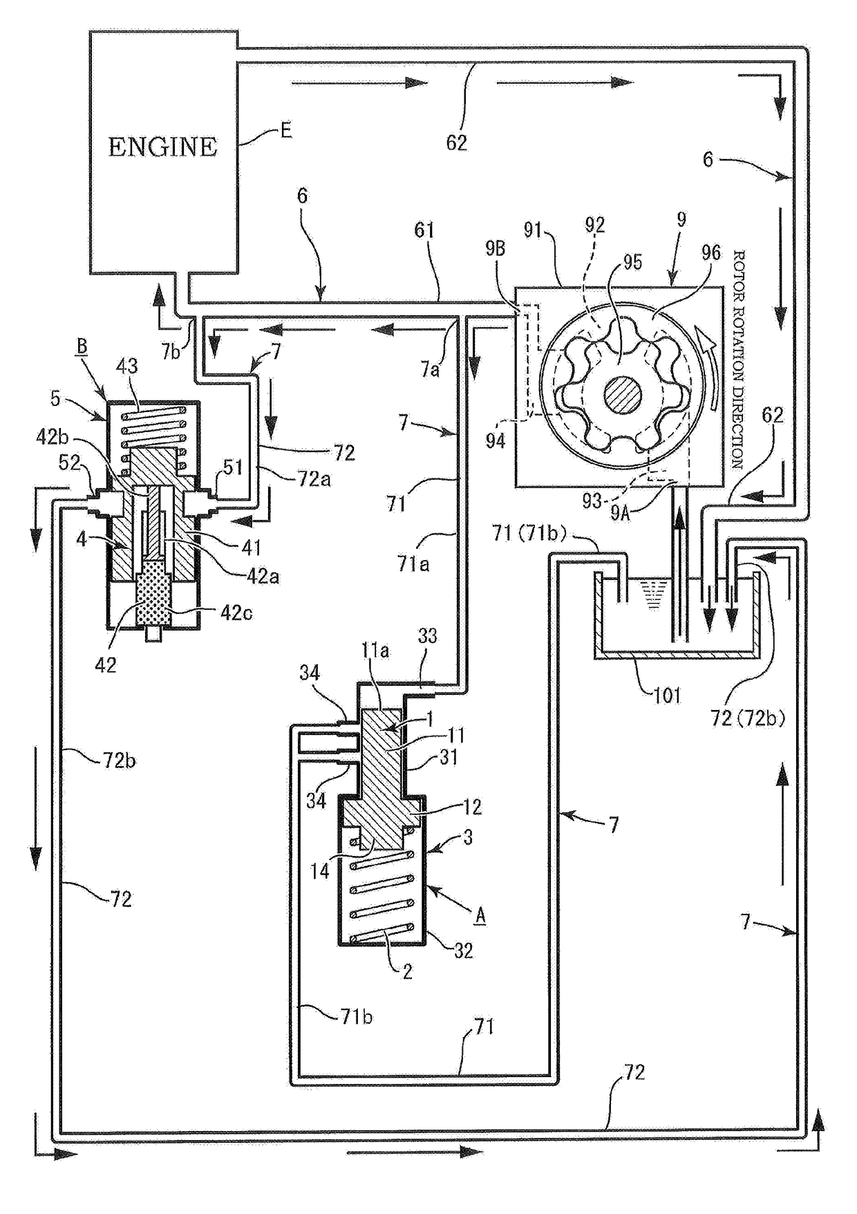
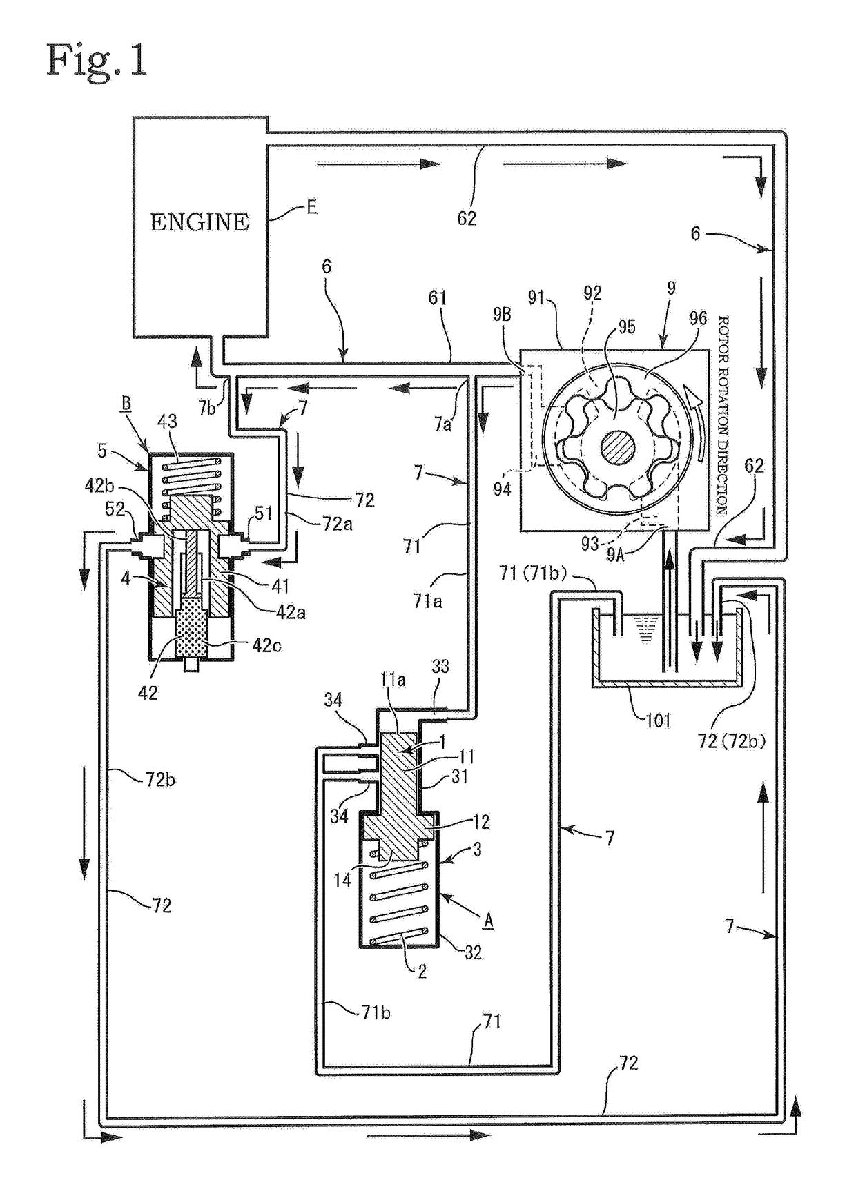
[0082]The configuration of the relief flow path 7 has two embodiments. In a first embodiment, the relief flow path 7 is divided into a first relief branch flow path 71 that branches off from the upstream flow path 61 via a first branch portion 7a at a position close to the side of the oil pump 9, and a second relief branch flow path 72 that branches off therefrom via a second branch portion 7b at a position close to the side of the engine E (see FIG. 1).
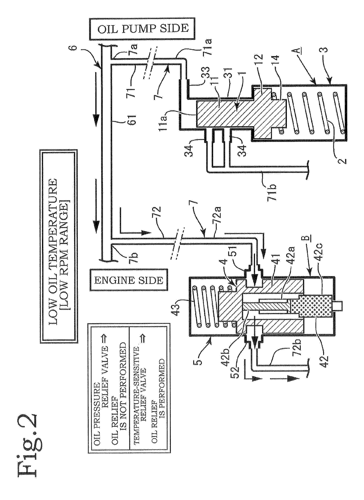
[0083]The first relief branch flow path 71 and the second relief branch flow path 72 are disposed in parallel, the oil pressure relief valve A is provided in the first relief branch flow path 71, and the temperature-sensitive relief valve B is provided in the second relief branch flow path 72. With this configuration, the oil pressure relief valve A and the temperature-sensitive relief valve B are disposed in parallel.
[0084]A flow path on the upstream side of the position where the oil pressure relief valve A is provided in the first...
second embodiment
[0086]The first relief branch flow path 71 and the second relief branch flow path 72 are capable of sending oil to the side of the intake portion 9A of the oil pump 9 via the oil pan 101. In the relief flow path 7, one upstream common flow path 73 that communicates with the side of the intake portion 9A of the oil pump 9 from the halfway location of the upstream flow path 61 of the oil circulation circuit 6 is provided, an upstream forked branch portion 7c is provided from the upstream common flow path 73, and the first relief branch flow path 71 and the second relief branch flow path 72 are provided from the upstream forked branch portion 7c so as to be disposed in parallel (see FIG. 8).
[0087]The oil pressure relief valve A is provided on one side of each of the first relief branch flow path 71 and the second relief branch flow path 72, and the temperature-sensitive relief valve B is provided on the other side thereof. A downstream forked confluence portion 7d is provided at the do...
PUM
 Abstract
Description
Claims
Application Information
 - R&D
- Intellectual Property
- Life Sciences
- Materials
- Tech Scout
- Unparalleled Data Quality
- Higher Quality Content
- 60% Fewer Hallucinations
Browse by: Latest US Patents, China's latest patents, Technical Efficacy Thesaurus, Application Domain, Technology Topic, Popular Technical Reports.
© 2025 PatSnap. All rights reserved.Legal|Privacy policy|Modern Slavery Act Transparency Statement|Sitemap|About US| Contact US: help@patsnap.com