
System of configuring active lighting to indicate directionality of an autonomous vehicle

a technology of active lighting and autonomous vehicles, applied in the direction of vehicular safety arrangements, electric devices, process and machine control, etc., can solve the problem that the passengers of autonomous vehicles may experience some uncertainty

Active Publication Date: 2017-05-04
ZOOX INC
View PDF0 Cites 124 Cited by
  • Summary
  • Abstract
  • Description
  • Claims
  • Application Information

AI Technical Summary

Benefits of technology

The patent text describes a system for implementing safety features in autonomous vehicles. The system includes various methods, systems, and apparatus for ensuring the vehicles operate safely and efficiently. The technical effects of the patent include improving operational status and intent of the autonomous vehicles, providing better communication for passengers, and enhancing the ability of the vehicles to navigate physical environments. The system also includes sensors and actuators to enable the vehicles to perceive and respond to changes in their surroundings. Overall, the patent aims to create a safer and more reliable autonomous vehicle system.

Problems solved by technology

Moreover, passengers of an autonomous vehicle may experience some uncertainty as to determining which autonomous vehicle is tasked to service their transportation needs.

Method used


Image

  • System of configuring active lighting to indicate directionality of an autonomous vehicle
  • System of configuring active lighting to indicate directionality of an autonomous vehicle
  • System of configuring active lighting to indicate directionality of an autonomous vehicle

Examples


Embodiment Construction

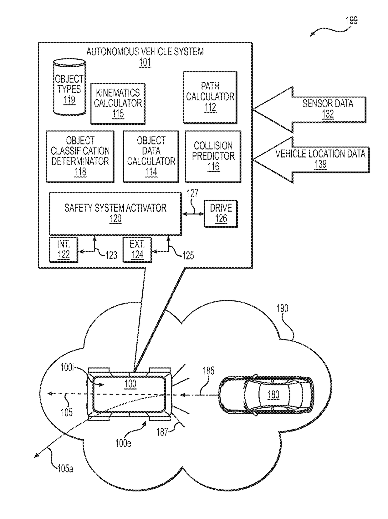
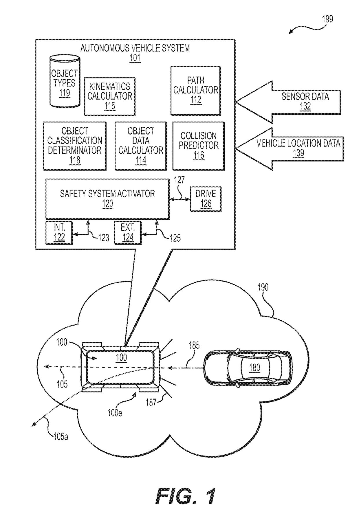
[0055]Various embodiments or examples may be implemented in numerous ways, including as a system, a process, a method, an apparatus, a user interface, software, firmware, logic, circuity, or a series of executable program instructions embodied in a non-transitory computer readable medium. Such as a non-transitory computer readable medium or a computer network where the program instructions are sent over optical, electronic, or wireless communication links and stored or otherwise fixed in a non-transitory computer readable medium. Examples of a non-transitory computer readable medium includes but is not limited to electronic memory, RAM, DRAM, SRAM, ROM, EEPROM, Flash memory, solid-state memory, hard disk drive, and non-volatile memory, for example. One or more non-transitory computer readable mediums may be distributed over a number of devices. In general, operations of disclosed processes may be performed in an arbitrary order, unless otherwise provided in the claims.

[0056]A detail...


PUM


Abstract

Systems, apparatus and methods may be configured to implement actively-controlled light emission from a robotic vehicle. A light emitter(s) of the robotic vehicle may be configurable to indicate a direction of travel of the robotic vehicle and / or display information (e.g., a greeting, a notice, a message, a graphic, passenger / customer / client content, vehicle livery, customized livery) using one or more colors of emitted light (e.g., orange for a first direction and purple for a second direction), one or more sequences of emitted light (e.g., a moving image / graphic), or positions of light emitter(s) on the robotic vehicle (e.g., symmetrically positioned light emitters). The robotic vehicle may not have a front or a back (e.g., a trunk / a hood) and may be configured to travel bi-directionally, in a first direction or a second direction (e.g., opposite the first direction), with the direction of travel being indicated by one or more of the light emitters.

Description

CROSS-REFERENCE TO RELATED APPLICATIONS[0001]This application is related to U.S. patent application Ser. No. ______ filed Nov. 4, 2015 (Attorney Docket No. ZOO-001) entitled “Autonomous Vehicle Fleet Service And System,” U.S. patent application Ser. No. ______ filed Nov. 4, 2015 (Attorney Docket No. ZOO-002) entitled “Adaptive Mapping To Navigate Autonomous Vehicles Responsive To Physical Environment Changes,” and U.S. patent application Ser. No. ______ filed Nov. 4, 2015 (Attorney Docket No. ZOO-022) entitled “Robotic Vehicle Active Safety Systems And Methods,” all of which are hereby incorporated by reference in their entirety for all purposes.FIELD[0002]Embodiments of the present application relate generally to methods, systems and apparatus for safety systems in robotic vehicles.BACKGROUND[0003]Autonomous vehicles, such as the type configured to transport passengers in an urban environment, may encounter many situations in which an autonomous vehicle ought to notify persons, veh...

Claims


Application Information

Patent Timeline
Patent Type & Authority Applications(United States)
IPC IPC(8): B60Q1/26B60Q1/52G05D1/00
CPCB60Q1/26B60Q1/525G05D1/0088G05D1/0027G05D1/0055G05D1/0248G05D1/0274G05D1/0297B60L3/0007B60L3/04B60L50/66B60N2/01566B60N2/42709B60N2/4279B60R21/01512B60R21/01546G01C21/32G01S5/16G08G1/205B60L2200/40B60Q1/507B60N2210/40B60N2/003B60N2230/20Y02P90/60Y02T10/70B60Q5/006G01S5/0018G01S2013/9316G06V20/56G08G1/20G09B9/04Y02T90/16G05D1/0255G05D1/0257B60W2554/00B60W2554/80B60W2420/403B60W2554/4041B60W2554/4026B60W60/0016B60W2554/20B60W2554/4023B60W2554/4044B60W2554/4029B60W60/0027B60W2420/408B60N2/002B60R21/01B60R2021/01272B60W10/18B60W10/30B60W30/08B60W30/095B60W2710/18B60W2710/30B60W10/04B60W10/20B60W30/09B60W30/0956B60W30/18B60W2400/00B60W2420/54B60W2710/06B60W2710/08B60W2710/20
Inventor KENTLEY, TIMOTHY DAVIDGAMARA, RACHAD YOUSSEF
Owner ZOOX INC
Learn More