
Vessel comprising cargo transloading system

a transloading system and cargo technology, applied in waterborne vessels, loading/unloading, cargo handling apparatuses, etc., can solve the problems of difficulty in operating cranes, transloaders being rolled, and infrastructures such as harbors or piers are very costly to build and maintain, so as to reduce the moving speed, reduce the risk of skidding, and the effect of reliable and energy-saving

Active Publication Date: 2017-05-04
MACGREGOR SWEDEN
View PDF0 Cites 2 Cited by
  • Summary
  • Abstract
  • Description
  • Claims
  • Application Information

AI Technical Summary

Benefits of technology

The invention allows for a larger capacity of a vessel without adding any extra weight during cargo transloading. The vessel can be positioned between two bararges, which makes it more efficient to operate the crane due to less adjustment of the luffing angle.

Problems solved by technology

Infrastructures, such as harbors or piers are very costly to build and to maintain.
The hoisting of cargo brings about that the transloader is subjected to a large tilting momentum which will result in that the transloader is rolled, i.e. tilted sideways.
A too large roll angle will bring about difficulties in operating the crane and will also render the security questionable.
Too large rolling angles will consequently render the transloader unusable.
A counterweight in an elevated position does however bring about stability issues due to the increased height of the mass center of the transloader.
Crane operation including adjustment of the luffing angle is time consuming bringing about a reduced overall capacity of the transloader.

Method used


Image

  • Vessel comprising cargo transloading system
  • Vessel comprising cargo transloading system
  • Vessel comprising cargo transloading system

Examples


Embodiment Construction

[0053]The present invention will now be described more fully hereinafter with reference to the accompanying drawings, in which preferred embodiments of the invention are shown. This invention may, however, be embodied in many different forms and should not be construed as limited to the embodiments set forth herein; rather, these embodiments are provided for thoroughness and completeness, and fully convey the scope of the invention to the skilled person.

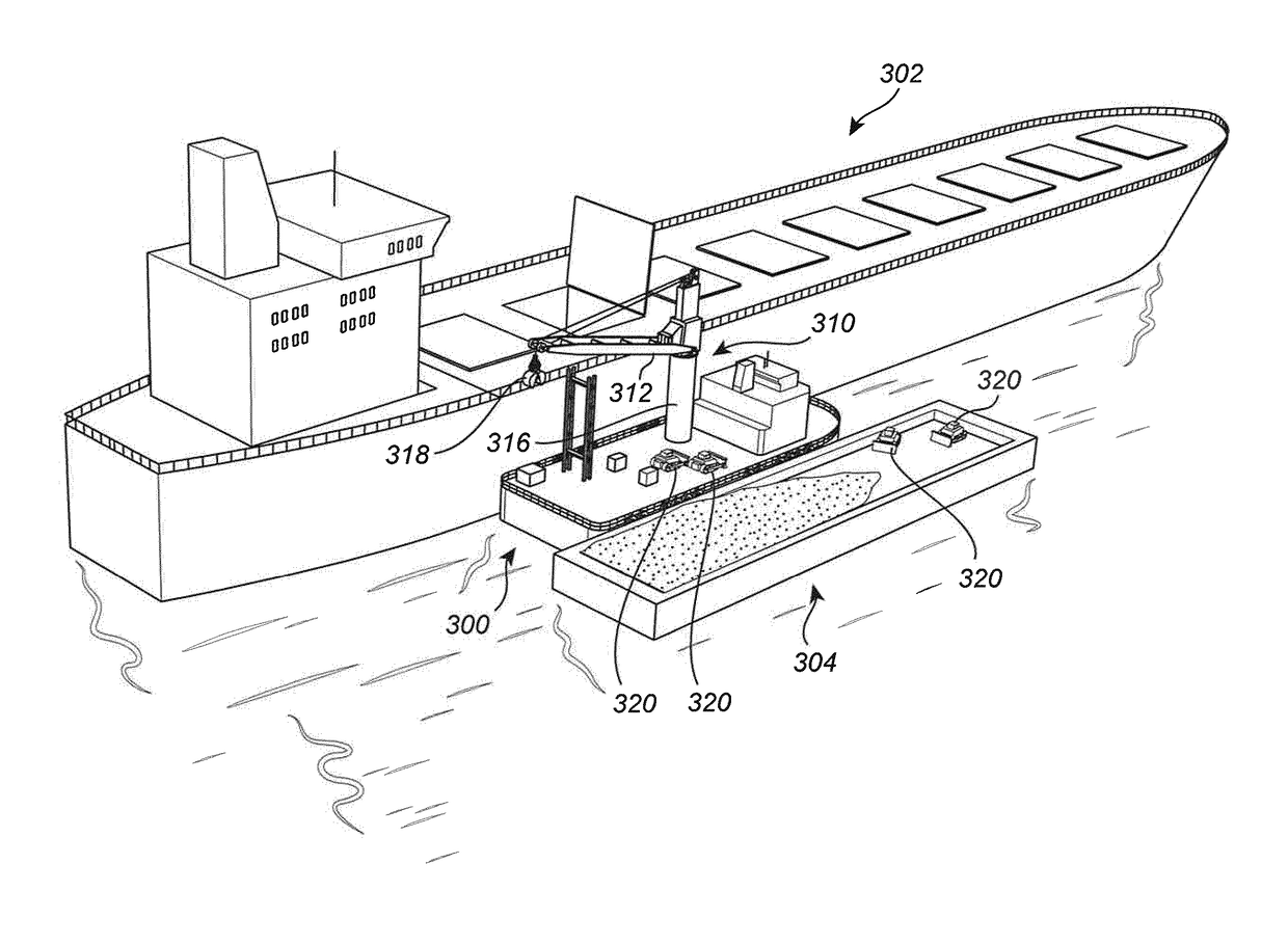
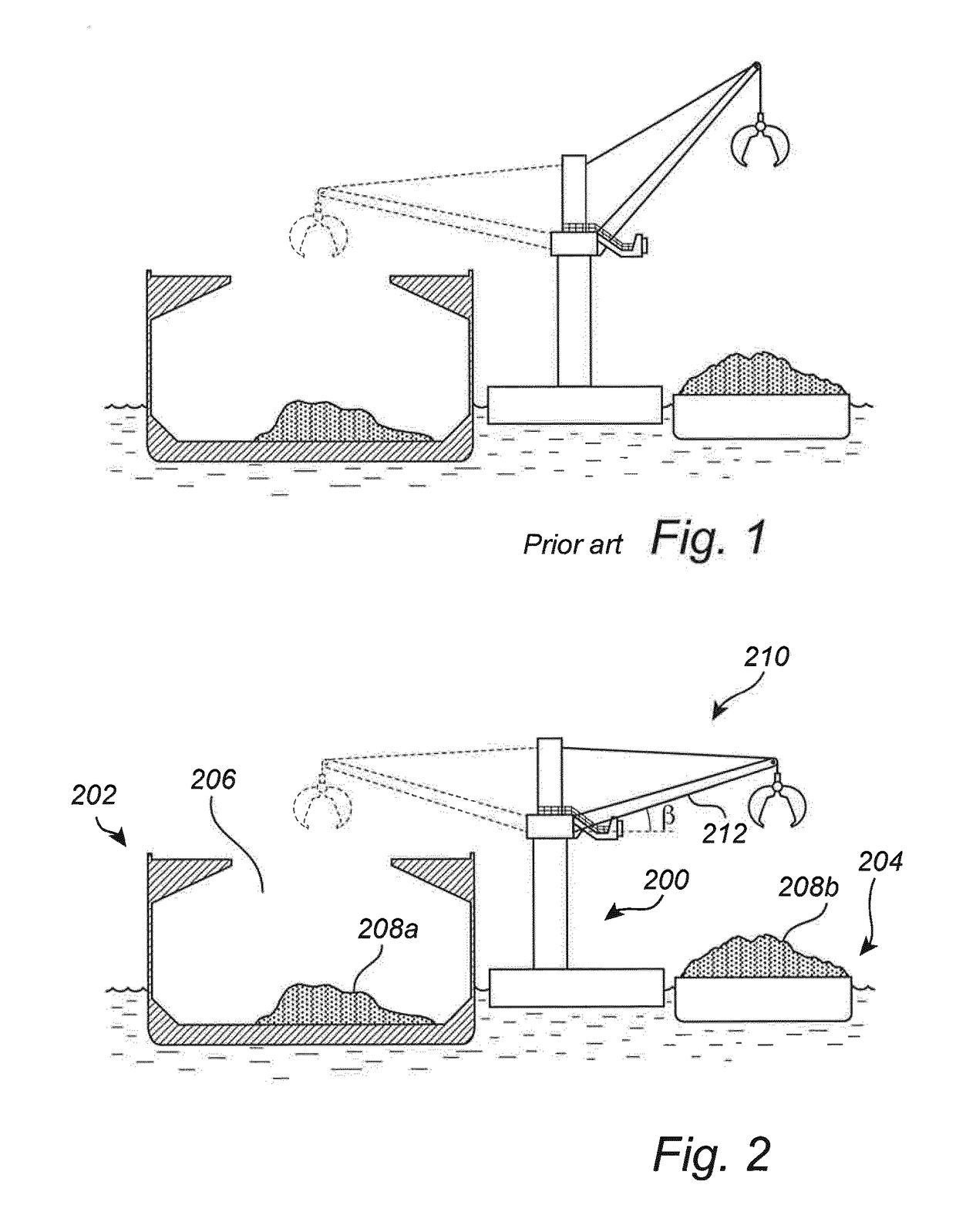
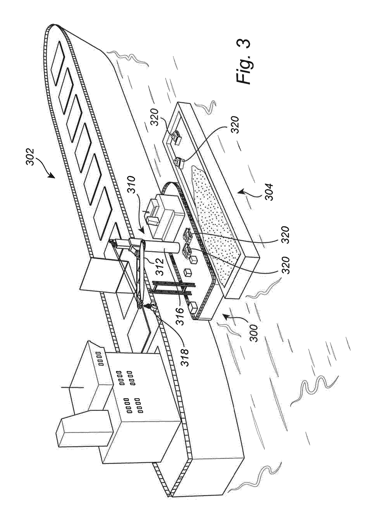
[0054]FIG. 2 illustrates a cross sectional view during transloading of cargo. Cargo is transloaded by means of a vessel 200 in accordance with the present invention in form of a transloader 200 which is positioned between an ocean going ship 202 and a barge 204 used for transferring cargo from a harbor. In the following detailed description, the inventive vessel 200 will be referred to as a transloader 200 for reasons of simplicity. In the illustrated cross sectional view, the cargo hold 206 of the ship 202 is partly filled with bulk...


PUM


Abstract

The present invention relates to a vessel (200, 300, 400, 600) comprising: a cargo transloading system, comprising: a crane (210, 310, 410, 610) supporting a cargo handling device (318, 418), and a counterweight arrangement (450, 550). The cargo handling device (318, 418) being rotatable about a vertical axis of rotation arranged with a first fixed offset in a first side direction with regard to a first vertical plane coinciding with a longitudinal centre axis (CA) of the vessel (200, 300, 400, 600). The counterweight arrangement (450, 550) comprising a weight (452, 552, 652) which is movable such that the mass centre (554) of the weight (452, 552, 652) is laterally displaceable between a first end position (556, 656) in which the mass centre (554) is arranged in the vicinity of the first vertical plane and a second end position (558, 658) in which the mass centre (554) is arranged with a second offset in a second side direction opposite to the first side direction with regard to the first vertical plane. The counterweight arrangement (450, 550) being arranged to move the weight (452, 552, 652) while the cargo handling device (318, 418) is rotated about the axis of rotation as a function of the rotation angle (a). The present invention also relates to a corresponding method and a use of the vessel (200, 300, 400, 600).

Description

TECHNICAL FIELD[0001]The present invention relates to a vessel comprising a cargo transloading system comprising a crane supporting a cargo handling device, and a counterweight arrangement. The invention also relates to a method for controlling a cargo transloading system for a vessel and a use of a vessel for transloading of cargo.BACKGROUND ART[0002]Today a substantial amount of cargo is shipped around the globe using large naval vessels or ships capable of traveling long distances over open sea.[0003]When shipping bulk cargo or load, such as coal or ore, large bulk naval vessels or ships dedicated for loading bulk cargo are commonly used due to their capability of loading bulk cargo. Bulk vessels are commonly equipped with large cargo holds which are covered by some form of hatch or cover which is opened during loading and unloading of the cargo concerned. When handling bulk cargo, cranes equipped with buckets or similar are commonly used to handle the cargo.[0004]Due to the subs...

Claims


Application Information

Patent Timeline
IPC IPC(8): B63B27/30B63B39/02B65G67/60B63B27/10
CPCB63B27/30B63B27/10B65G2814/0397B65G67/60B63B2734/00B63B39/02
Inventor WALLIN, TOMAS
Owner MACGREGOR SWEDEN
Learn More