See-through holographic display apparatus

a display apparatus and see-through technology, applied in the field of see-through holographic display apparatuses, can solve problems such as visual fatigu

Active Publication Date: 2017-05-04
SAMSUNG ELECTRONICS CO LTD
View PDF1 Cites 34 Cited by
  • Summary
  • Abstract
  • Description
  • Claims
  • Application Information

AI Technical Summary

Problems solved by technology

However, the related art HMD for VR is based on the stereoscopy technology, which causes visual fatigue due to a vergence-accommodation conflict.
The related art HMD for VR may also cause problems when applied to spatial interaction technology.
Also, the exemplary embodiments are not required to overcome the disadvantages described above, and an exemplary embodiment may not overcome any of the problems described above.

Method used


Image

  • See-through holographic display apparatus
  • See-through holographic display apparatus
  • See-through holographic display apparatus

Examples


Embodiment Construction

[0048]Certain exemplary embodiments are described in greater detail below with reference to the accompanying drawings.

[0049]In the following description, the same drawing reference numerals are used for the same elements even in different drawings. The matters defined in the description, such as detailed construction and elements, are provided to assist in a comprehensive understanding of exemplary embodiments. Thus, it is apparent that exemplary embodiments can be carried out without those specifically defined matters. Also, well-known functions or constructions are not described in detail since they would obscure exemplary embodiments with unnecessary detail.

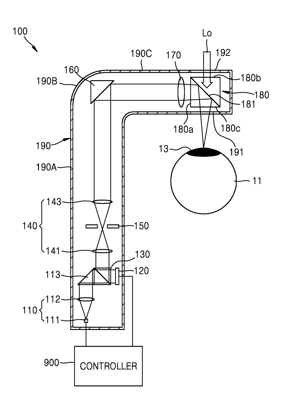
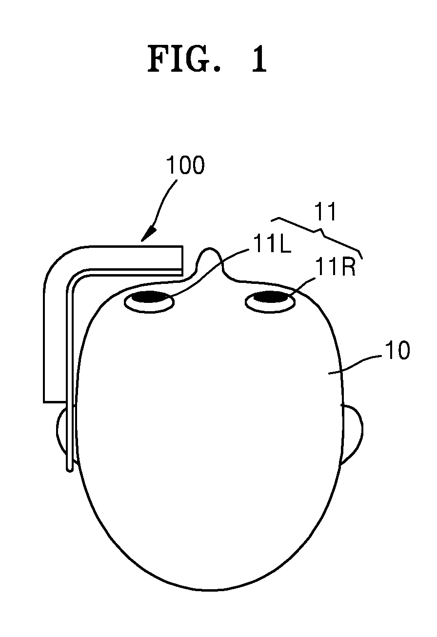
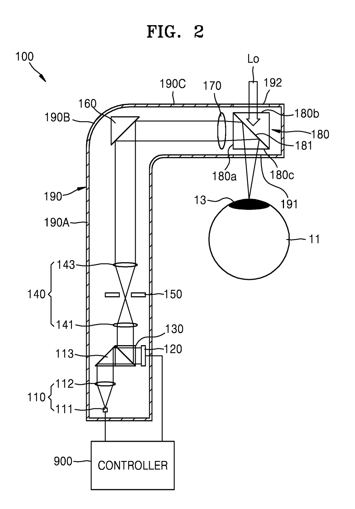
[0050]FIG. 1 is a schematic diagram of an example of a see-through holographic display apparatus 100 worn by a user 10, i.e., a viewer, according to an exemplary embodiment. FIG. 2 is a schematic diagram of a relay optical system 140 of the see-through holographic display apparatus 100 of FIG. 1.

[0051]Referring to FIG. 1, the ...


PUM


Abstract

A see-through holographic display apparatus includes a relay optical system expanding or reducing and transferring a hologram image generated by a spatial light modulator, a noise removal filter removing noise from diffraction light of the hologram image transferred through the relay optical system, and a light path converter changing at least one of a path of the diffraction light of the hologram image transferred from the relay optical system and a path of external light.

Description

CROSS-REFERENCE TO RELATED APPLICATIONS[0001]This application claims priority from Korean Patent Application No. 10-2015-0150272, filed on Oct. 28, 2015 and Korean Patent Application No. 10-2016-0055766, filed on May 4, 2016, in the Korean Intellectual Property Office, the disclosures of which are incorporated herein in their entireties by reference.BACKGROUND[0002]1. Field[0003]Apparatuses and methods consistent with exemplary embodiments relate to a holographic display apparatus, and more particularly to a see-through holographic display apparatus via which a hologram image and the outside view are simultaneously or selectively seen.[0004]2. Description of the Related Art[0005]As many three-dimensional (3D) movies have emerged, research into technology relating to 3D image display apparatuses has been carried out. For example, research into apparatuses for implementing a high quality hologram in real time by using a spatial light modulator has been actively conducted.[0006]Further...

Claims


Application Information

Patent Timeline
Patent Type & Authority Applications(United States)
IPC IPC(8): G02B27/01G02B3/14G03H1/22
CPCG02B27/0103G03H1/2294G03H1/2205G02B3/14G02B27/0172G02B2027/0178G03H2001/2207G03H2223/50G03H2223/20G03H2225/36G02B2027/0174G03H2001/221G02B2027/0134G03H2001/2284
Inventor SUNG, GEEYOUNGKIM, YUNTAEAN, JUNGKWUENLEE, HONGSEOK
Owner SAMSUNG ELECTRONICS CO LTD
Why Eureka
Try Eureka