Power tool

a technology of power tools and tools, applied in the field of power tools, can solve the problems of increasing size and cost, increasing the complexity of the motor control, etc., and achieve the effect of reducing cost and simplifying the structure of the lock-on mechanism

Active Publication Date: 2017-05-04
MAKITA CORP
View PDF36 Cites 12 Cited by
  • Summary
  • Abstract
  • Description
  • Claims
  • Application Information

AI Technical Summary

Benefits of technology

[0006]According to the first aspect of the disclosure, as a means for releasing or disabling the lock-ON state of the start switch, the electromagnetic actuator is preferably designed such that, if the supply of electric current is cut off (interrupted), then the actuation pin is actuated (moved) in the pushed out direction. Thus, when the supply of electric power is cut off, such as in a power failure, the actuation pin of the electromagnetic actuator is pushed out from (advanced out of) a body of the electromagnetic actuator and the lock-ON state of the start switch is released or disabled. Therefore, when the supply of electric power subsequently returns (resumes), the electric motor does not start, thereby preventing an inadvertent startup of the power tool. The power tool according to the first aspect of the disclosure is preferably configured such that the lock-ON state of the start switch is released or disabled by utilizing the actuation of the electromagnetic actuator; i.e. it is not configured in an actuation control of the electric motor, as in the above-described known art. Therefore, the controller that controls the actuation (driving) of the electric motor can be made more compact and, consequently, the power tool can be reduced in size and cost.
[0008]According to the second aspect of the disclosure, as a means for releasing or disabling the lock-ON state of the start switch, the electromagnetic actuator is preferably designed such that, if the supply of electric current is cut off, then the actuation pin is retracted or pulled into the body of the electromagnetic actuator. When the supply of electric power is cut off, such as in a power failure, the actuation pin of the electromagnetic actuator retracts and the lock-ON state of the start switch is released or disabled. Therefore, when the supply of electric power subsequently returns (resumes), the electric motor does not start, thereby preventing an inadvertent startup of the power tool. Thus, the power tool according to the second aspect of the disclosure is also preferably configured such that the lock-ON state of the start switch is released or disabled by utilizing the actuation of the electromagnetic actuator; i.e. it is also not configured in an actuation control of the electric motor, as in the above-described known art. Therefore, in the second aspect as well, the controller that controls actuation (driving) of the electric motor can be made more compact and, consequently, the power tool can be reduced in size and cost.
[0010]According to the third aspect of the disclosure, the electric motor can be started by the start switch being slid to the ON position. Then, by tilting the start switch while it is at the ON position, and engaging the lock part with the support-pedestal part, the start switch can be locked (mechanically engaged) at (in) the ON position. When the supply of electric current is cut off, the lock-ON state of the start switch is physically (mechanically) released (disengaged) by the actuation of the electromagnetic actuator, and thereby the power tool is prevented from inadvertently starting when the supply of electric current subsequently resumes.
[0012]According to the fourth aspect of the disclosure, the degrees of freedom in the arrangement of the electromagnetic actuator can be increased. In addition, the thrust of the actuation pin of the electromagnetic actuator is amplified by the leverage of the intermediate lever and that thrust can be used as the operating force that releases or disables the lock-ON state of the start switch. Therefore, the electromagnetic actuator can be reduced in size. Furthermore, by changing or shifting the positional relationship between a tilt fulcrum of the intermediate lever and the point of contact on the start switch, any type of electromagnetic actuator that either pulls in (retracts) or pushes out (advances) in response to the cutoff of the electric current supply can be selected and utilized in an unrestricted manner.
[0014]According to the fifth aspect of the disclosure, because the start switch directly engages or latches the actuation pin of the electromagnetic actuator, which is, e.g., in a state of being pushed out owing to the supply of electric current, in the lock-ON state, the start switch is locked at (in) the ON position by the actuation pin. In this lock-ON state, when the supply of electric current to the electromagnetic actuator is cut off by the cutoff of the supply of electric power to the power tool, the actuation pin is pulled in (retracted) and disengages or unlatches from the start switch, thereby releasing or disabling the lock-ON state of the start switch. According to the fifth aspect of the invention, because a configuration is provided in which the start switch directly engages with the actuation pin, the configuration (structural elements) of the lock-ON mechanism can be simplified and reduced in cost more than in a configuration in which the start switch is indirectly engaged via one or more other structural elements, such as an intermediate lever.

Problems solved by technology

However, when such a lock-ON feature (function) is provided, it is necessary to reliably prevent the situation from arising in which the lock-ON state is not released (disabled) when the supply of electric power is cut off, e.g., during a power failure, because the motor will inadvertently restart after the supply of electric power returns (resumes) if the start switch remains in the lock-ON state.
In the above-described known art, because the release (disabling) of the lock-ON function when the electric power is cut off is configured in an electrical manner under motor control, the increased complexity of the motor control leads to an increase in size and cost.

Method used


Image

  • Power tool
  • Power tool
  • Power tool

Examples


first embodiment

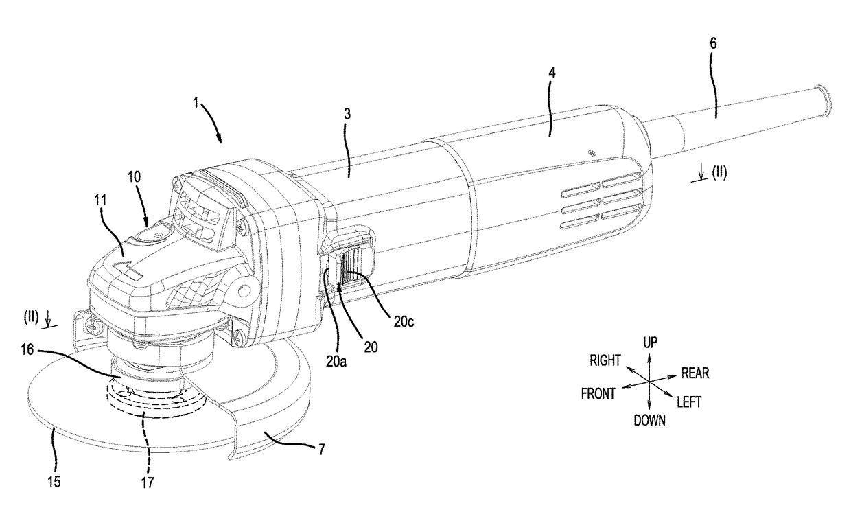
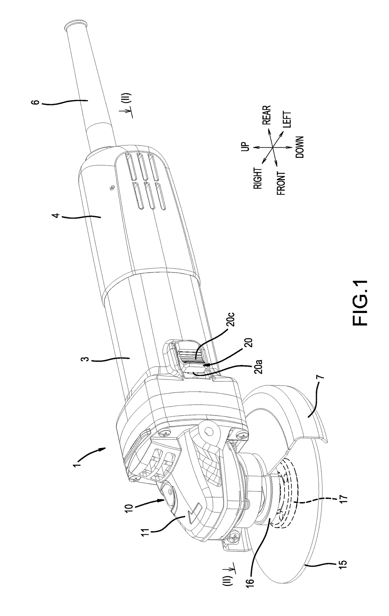
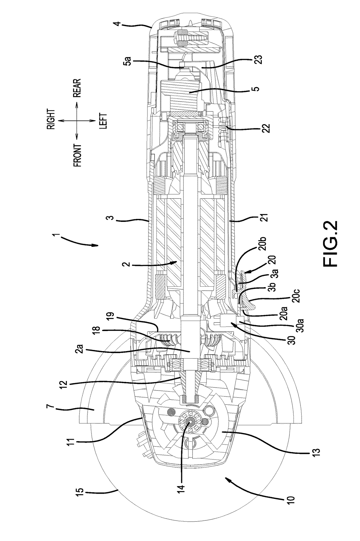
[0032]Next, embodiments of the present disclosure will be explained with reference to FIGS. 1 to 17, in which a disc grinder will be utilized as one representative, non-limiting example of a power tool 1 according to the present teachings. FIGS. 1-5 show a power tool 1 according to a In the first exemplary power tool 1, an electric motor 2, which serves as a drive source, is built into (mounted or disposed within) a main-body housing 3. The main-body housing 3 has a substantially cylindrical shape of a size that is easy to grip by a user. The user grips the main-body housing 3 and is positioned (stands) rearward (the right side in FIG. 1 and FIG. 2) of the power tool 1. Hereinbelow, the front, rear, left, and right directions of members, structural elements, and the like are denoted with reference to a user holding the power tool 1 in a normal operating state.

[0033]A rear-part case 4 is joined to a rear part of the main-body housing 3. A switch main body (power switch) 5 is housed ...

second embodiment

[0057]The second embodiment thus also has a configuration in which, when the supply of electric power is cut off, the lock-ON state of the start switch 20 is released (disabled) by the movement of the actuation pin 40a of the electromagnetic actuator 40. Therefore, the controller for motor control can be simplified and made more compact as compared with the configuration in which the lock-ON state is electrically released in the actuation control of the electric motor, as in the above-described known example.

[0058]In addition, when the power-supply cord 6 is pulled out of the power-supply outlet after usage of the power tool 1 has concluded, the actuation pin 40a of the electromagnetic actuator 40 will be held in the pushed out (advanced) state (i.e. it is maintained in the pushed out or advanced position). Therefore, the engaging part 41a of the intermediate lever 41 remains at the front side of the end part of the support-pedestal part 3a. Consequently, the start switch 20 cannot ...

third embodiment

[0063] a configuration is again adopted in which the lock-ON state of the start switch 20 is released (disabled) by the electromagnetic actuator (50), and therefore the controller for motor control can be simplified and made more compact as compared with the above-described known configuration in which the lock-ON state is electronically released in the actuation control of the electric motor.

[0064]In addition, according to the third embodiment as well, when the supply of electric power is cut off (interrupted), the start switch 20 cannot be pushed into the lock-ON position. Therefore, even if some other member (structure) or a person interferes with (accidentally pushes) the start switch 20 when the power tool 1 is not being used for workpiece processing (e.g., during storage), the start switch 20 can not be put (intentionally or unintentionally) into the lock-ON state. Consequently, the power tool 1 will not inadvertently start when the supply of electric power is subsequently con...


PUM


Abstract

A power tool (1) includes an electric motor (2) as a drive source and a start switch (20; 61) that starts the electric motor (2) and is lockable in an ON position in a lock-ON state. An electromagnetic actuator (30; 40; 50; 60) pushes out or pulls in an actuation pin (30a; 40a; 50a; 60a) with respect to a body of the electromagnetic actuator (30; 40; 50; 60) in response to cutting off of a supply of electrical current to the power tool (1). The pushed-out or pulled-in actuation pin, directly or indirectly, disengages the start switch (20; 61) from the lock-ON state and / or prevents the start switch (20; 61) from being shifted into the lock-ON state.

Description

CROSS-REFERENCE[0001]This application claims priority to Japanese patent application no. 2015-211414 filed on Oct. 28, 2015, the contents of which are fully incorporated herein by reference.TECHNICAL FIELD[0002]The present disclosure relates to a power tool such as a disc grinder.BACKGROUND ART[0003]In a disc grinder used for cutting, grinding, and / or performing other operations on stone, concrete, or the like, switching a start switch to the ON side (ON position) starts an electric motor and thereby rotates a circular grinding wheel. The start switch is configured such that it can be locked (a so-called “lock-ON” function or feature) in the actuated or ON state so that the user is not required to continuously hold the start switch in the ON position while using the grinder to process a workpiece, thereby facilitating the processing work. Japanese Laid-open Patent Publication 2012-76160 and its English counterpart US 2013 / 0186661 disclose a technique in which the lock-ON function of...

Claims


Application Information

Patent Timeline
Patent Type & Authority Applications(United States)
IPC IPC(8): H01H25/00H01H21/00H01H9/06H01H9/20B24B23/02B25F5/02
CPCH01H25/00B24B23/028B25F5/02H01H9/06H01H9/20H01H21/00H01H2001/508B24B55/00B25F5/00
Inventor HANAI, TAKAMASASUNABE, HIKARUNINAGAWA, SATOSHINAKAMURA, SHINNAKAHAMA, MASATOSHIFUKUDA, KAZUSAMIYATA, KENICHI
Owner MAKITA CORP
Why Eureka
Try Eureka