Systems and methods for fracturing a multiple well pad

Active Publication Date: 2017-05-11
VAULT PRESSURE CONTROL LLC
View PDF5 Cites 11 Cited by
  • Summary
  • Abstract
  • Description
  • Claims
  • Application Information

AI Technical Summary

Benefits of technology

The present invention provides a flow system for use at a hydraulic fracturing well site. This system includes a tree, an inlet head, and a fluid conduit with a valve for controlling fluid flow through the conduit. The system can have a single tree or multiple trees, with separate valves for each tree. The method involves pressurizing fluid and directing it through the conduit and valves to the well for fracturing. The technical effects of this invention include the ability to efficiently direct fluid to multiple wells for fracturing, reducing fluid waste and lowering costs.

Problems solved by technology

One disadvantage to typical hydraulic fracturing spreads is that, when servicing multiple wells, the hydraulic fracturing, or zipper manifold, is typically located near the missile, and some distance from some or all of the wells.
Thus, piping connecting the manifold to the trees of individual wells can be lengthy, and include many turns and bends.
Such turns and bends lead to inefficiencies, and often require couplings and fittings that add possible failure points to the system.

Method used


Image

  • Systems and methods for fracturing a multiple well pad
  • Systems and methods for fracturing a multiple well pad
  • Systems and methods for fracturing a multiple well pad

Examples


Embodiment Construction

[0020]The foregoing aspects, features and advantages of the present technology will be further appreciated when considered with reference to the following description of preferred embodiments and accompanying drawings, wherein like reference numerals represent like elements. In describing the preferred embodiments of the technology illustrated in the appended drawings, specific terminology will be used for the sake of clarity. The invention, however, is not intended to be limited to the specific terms used, and it is to be understood that each specific term includes equivalents that operate in a similar manner to accomplish a similar purpose.

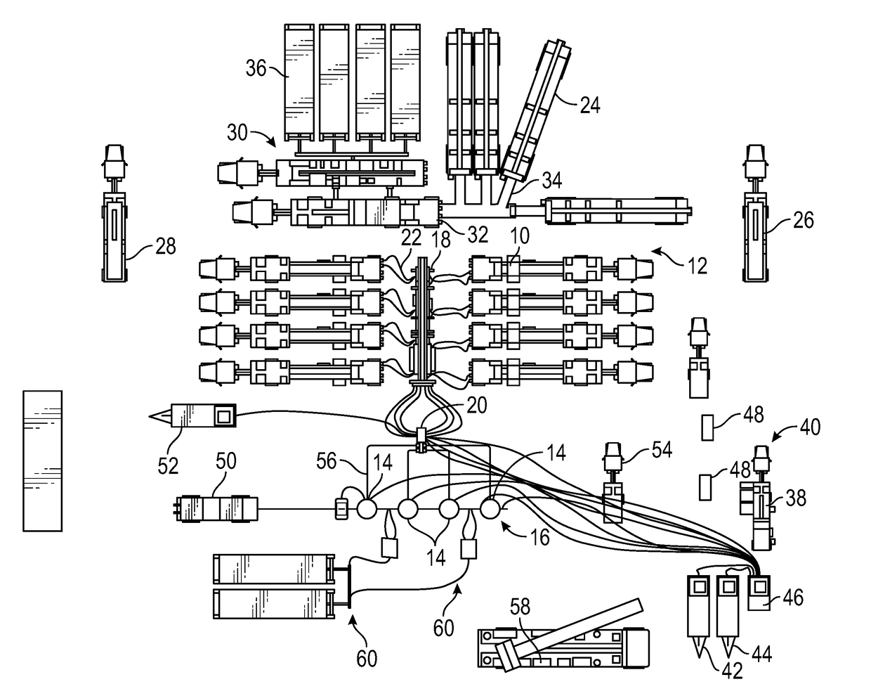
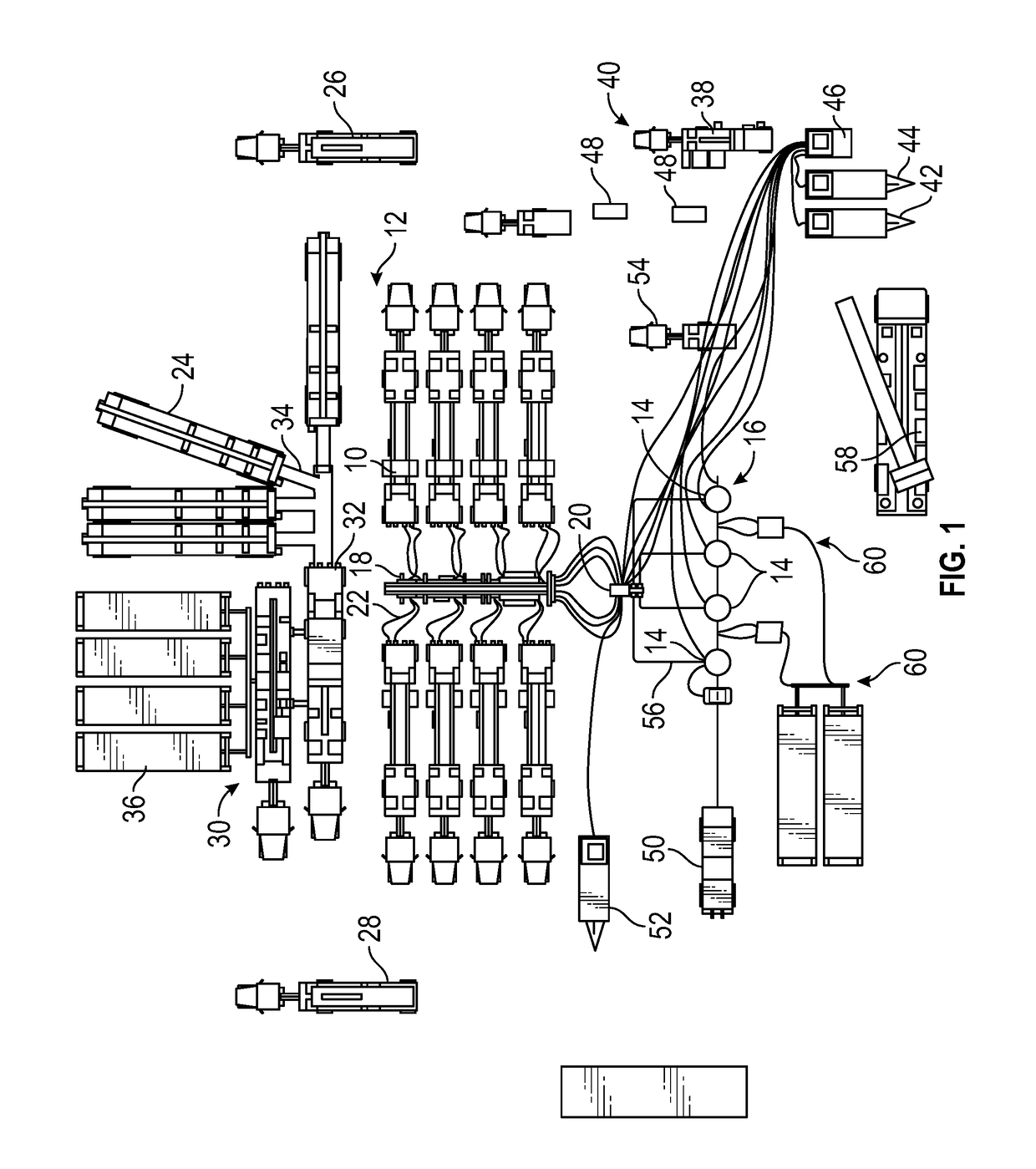
[0021]FIG. 1 shows a schematic environmental view of equipment used in a hydraulic fracturing operation. Specifically, there is shown a plurality of pumps 10 mounted to vehicles 12, such as trailers. The pumps 10 are fluidly connected to trees 14 attached to wellheads 16 via a missile 18, which is in turn connected to an inlet head 20. As shown,...


PUM


Abstract

A flow system for use at a hydraulic fracturing well site, including a tree attached to a wellhead, an inlet head in fluid communication with at least one hydraulic fracturing pump at the well site, and an adjustable fluid conduit providing fluid communication between the inlet head and the tree. The flow system further includes a valve in the fluid conduit and having an open position and a closed position, the valve permitting fluid flow through the fluid conduit when in the open position, and preventing fluid flow through the fluid conduit when in the closed position, at least a portion of the fluid conduit positioned between the valve and the tree.

Description

CROSS REFERENCE TO RELATED APPLICATIONS[0001]This application claims priority to and the benefit of, co-pending U.S. Provisional Application Ser. No. 62 / 251,413, filed Nov. 5, 2015, the full disclosure of which is hereby incorporated herein by reference in its entirety for all purposes.BACKGROUND[0002]Field of Invention[0003]This invention relates in general to equipment used in the hydrocarbon industry, and in particular, to systems and methods for hydraulic fracturing operations.[0004]Description of the Prior Art[0005]Hydraulic fracturing is a technique used to stimulate production from some hydrocarbon producing wells. The technique usually involves injecting fluid, or slurry, into a wellbore at a pressure sufficient to generate fissures in the formation surrounding the wellbore. The fracturing fluid slurry, whose primary component is usually water, includes proppant (such as sand or ceramic) that migrate into the fractures with the fracturing fluid slurry and remain to prop open...

Claims


Application Information

Patent Timeline
IPC IPC(8): E21B34/02E21B17/02E21B33/068E21B43/26
CPCE21B34/02E21B33/068E21B17/02E21B43/26E21B43/2607
Inventor KAJARIA, SAURABHCHEATHAM, LLOYD RAY
Owner VAULT PRESSURE CONTROL LLC
Why Eureka
Try Eureka