Fuel rail

a fuel rail and accumulator technology, applied in the field of fuel rails, can solve the problems of adding stress on the fasteners, the configuration of the securement between the pressure accumulator and the fuel rail, etc., and achieve the effect of improving the overall functionality of the fuel rail

Inactive Publication Date: 2017-05-11
BENTELER AUTOMOBILTECHNIK GMBH
View PDF10 Cites 6 Cited by
  • Summary
  • Abstract
  • Description
  • Claims
  • Application Information

AI Technical Summary

Benefits of technology

[0022]According to another advantageous feature of the present invention, a coupling piece made of a same material as the tubular body and in one piece with the tubular body can be provided for securing an attachment piece. This further enhances overall functionality of a fuel rail according to the present invention. The coupling piece may be provided for receiving a sleeve and screw connectors, via which a further system component, e.g. an intake module on the fuel rail, can be mounted.

Problems solved by technology

Especially difficult is the configuration of the securement between pressure accumulator pipe and cylinder head, when to be realized at an oblique angle.
This adds to stress on the fasteners.

Method used


Image

  • Fuel rail
  • Fuel rail
  • Fuel rail

Examples


Embodiment Construction

[0028]Throughout all the figures, same or corresponding elements may generally be indicated by same reference numerals. These depicted embodiments are to be understood as illustrative of the invention and not as limiting in any way. It should also be understood that the figures are not necessarily to scale and that the embodiments may be illustrated by graphic symbols, phantom lines, diagrammatic representations and fragmentary views. In certain instances, details which are not necessary for an understanding of the present invention or which render other details difficult to perceive may have been omitted.

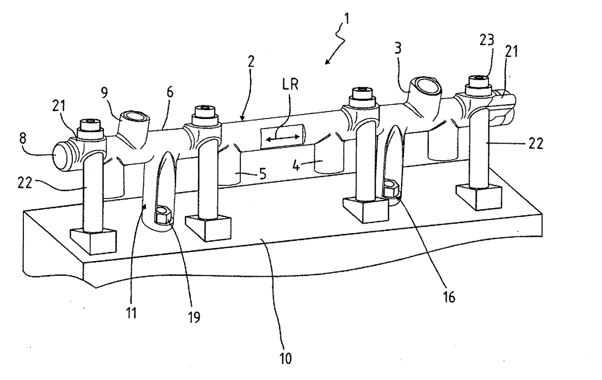
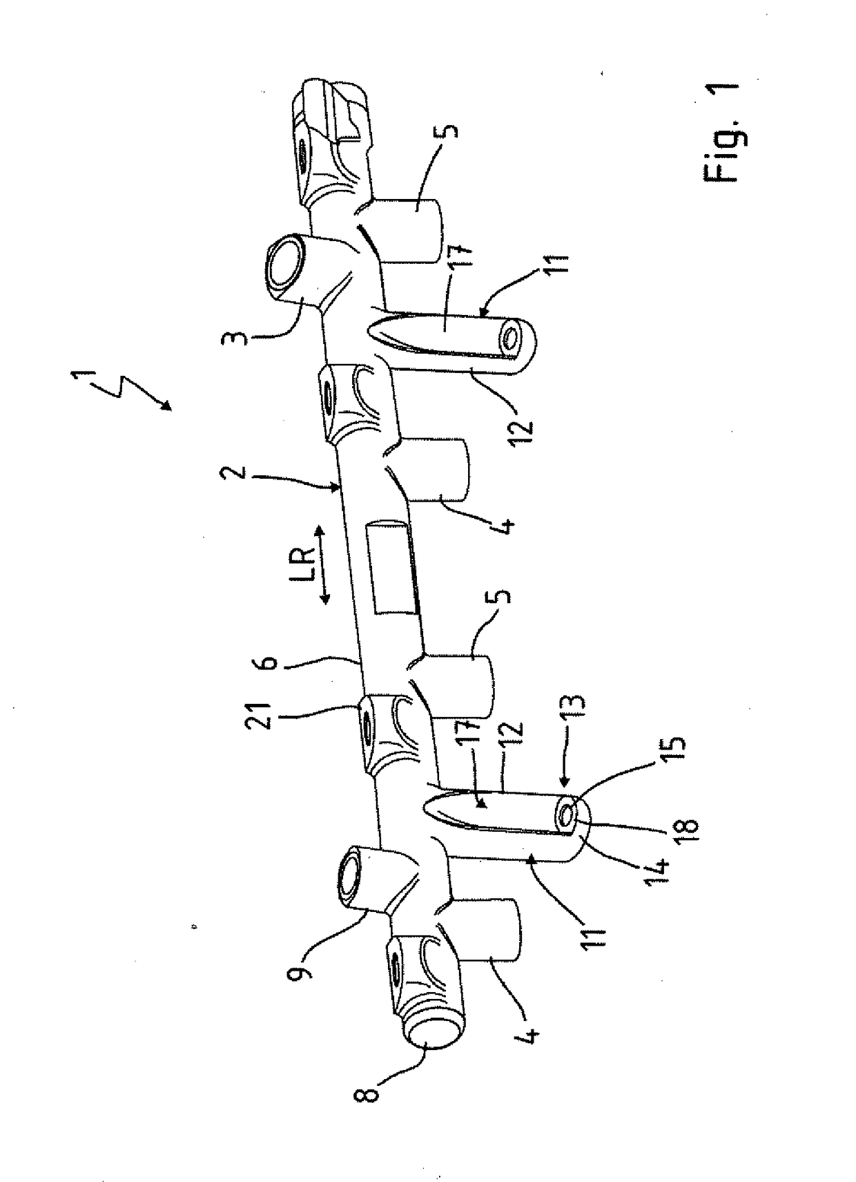
[0029]Turning now to the drawing, and in particular to FIG. 1, there is shown a perspective illustration of a fuel rail according to the present invention, generally designated by reference numeral 1. The fuel rail 1 is a component of an accumulator injection system of a combustion engine. Pressure generation and fuel injection are decoupled from one another in such an accumulator ...


PUM


Abstract

A fuel rail includes a pressure accumulator pipe which is configured to receive fuel under pressure and includes a forged tubular body. Made in one piece with the tubular body is an injector mount. A support arranged on the tubular body extends in alignment with the injector mount, with a screw fastener configured to secure the pressure accumulator pipe via the support to a cylinder head of an internal combustion engine.

Description

CROSS-REFERENCES TO RELATED APPLICATIONS[0001]This application claims the priority of German Patent Application, Serial No. 20 2015 105 989.2, filed Nov. 9, 2015, pursuant to 35 U.S.C. 119(a)-(d), the disclosure of which is incorporated herein by reference in its entirety as if fully set forth herein.BACKGROUND OF THE INVENTION[0002]The present invention relates to a fuel rail.[0003]The following discussion of related art is provided to assist the reader in understanding the advantages of the invention, and is not to be construed as an admission that this related art is prior art to this invention.[0004]A fuel rail is a component of a fuel supply or fuel injection system and is provided to feed fuel to injection valves of a combustion engine. Statically compressed fuel is hereby stored in a pressure accumulator pipe from where fuel is distributed to the injectors or injection valves of a cylinder bank.[0005]Substantial pressures are encountered within the fuel injection system and i...

Claims


Application Information

Patent Timeline
Patent Type & Authority Applications(United States)
IPC IPC(8): F02M55/02F02M61/14
CPCF02M61/14F02M55/025F02M55/02F02M2200/855F02M2200/857F02M69/465
Inventor SCHULTZ, JONAS
Owner BENTELER AUTOMOBILTECHNIK GMBH
Why Eureka
Try Eureka