Machine tool

a technology of machine tools and rotation wheels, applied in the field of machine tools, can solve the problems of difficulty in a worker to seek and set the appropriate variation, and achieve the effect of reducing chatter vibration, reducing vibration, and easy setting of similar parameters

Active Publication Date: 2017-05-11
OKUMA CORP
View PDF4 Cites 4 Cited by
  • Summary
  • Abstract
  • Description
  • Claims
  • Application Information

AI Technical Summary

Benefits of technology

[0015]With the machine tool according to the disclosure, the rotation speed for efficiently reducing a chatter vibration, a variation width of the rotation speed, and similar parameter can be easily set.

Problems solved by technology

Then, it is relatively difficult for a worker to seek and set the appropriate variation width by the workpieces.

Method used


Image

  • Machine tool
  • Machine tool
  • Machine tool

Examples


Embodiment Construction

[0020]The following describes examples of an embodiment of the disclosure based on the drawings as necessary. The embodiment of the disclosure is not limited to the following examples.

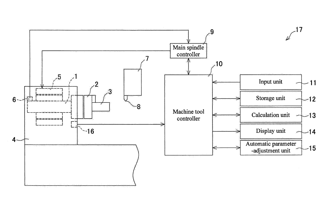
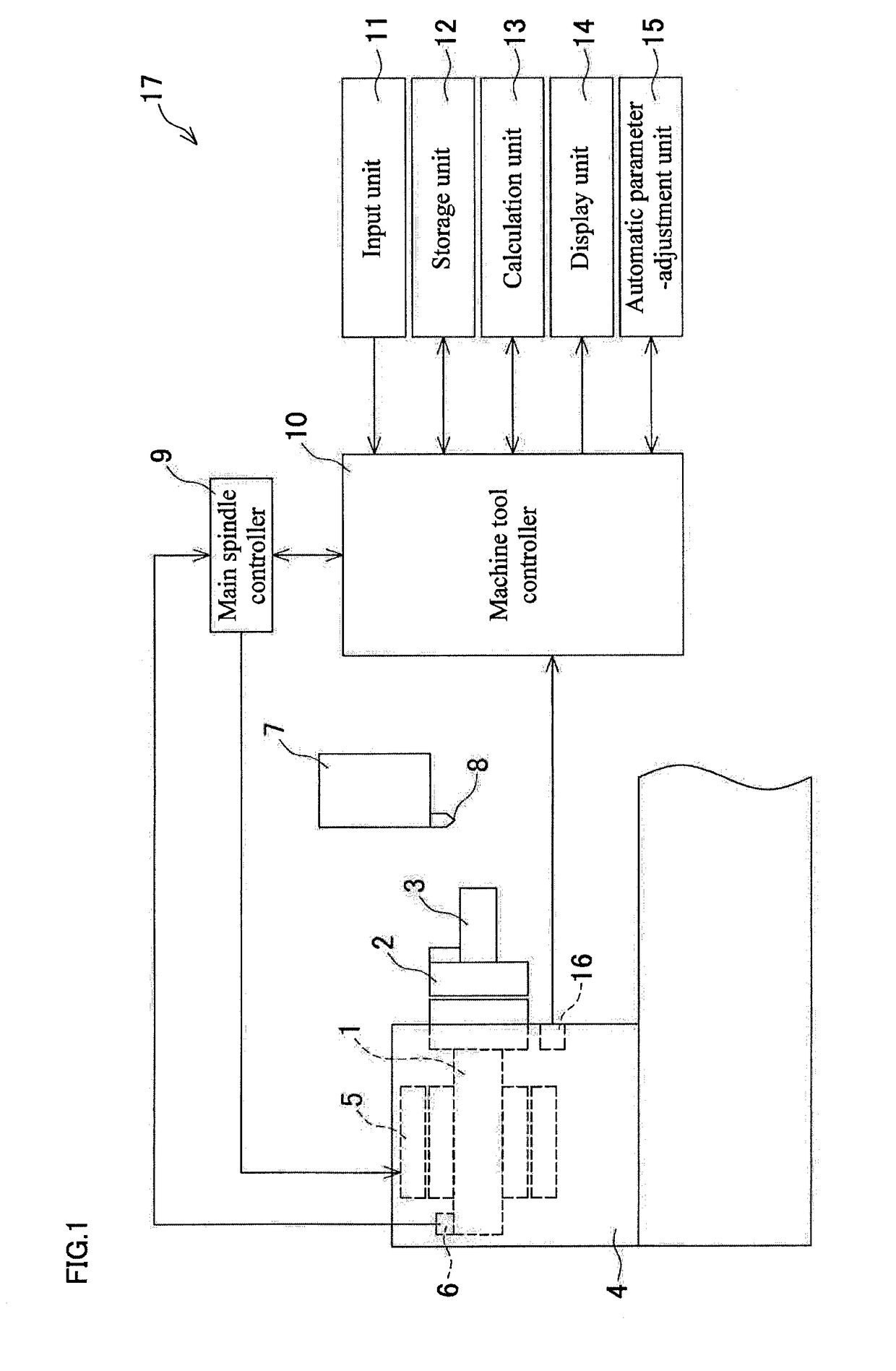
[0021]FIG. 1 is a schematic diagram of a machine tool 17 according to the embodiment. The machine tool 17 includes a main spindle 1 that includes a chuck 2 as a gripping unit on a distal end. The chuck 2 is configured to grip a shaft-shaped workpiece 3. The main spindle 1 is rotatably supported by a headstock 4. The headstock 4 includes a motor 5 for rotating the main spindle 1 and an encoder 6 for detecting a rotation speed of the main spindle 1. The encoder 6 is used by a main spindle controller 9 as a rotation speed control unit to monitor the rotation speed of the main spindle 1 and control the rotation speed of the main spindle 1. The machine tool 17 includes a tool post 7 configured to operate in a radial direction and a longitudinal direction of the workpiece 3. A tool 8 is secured to the tool p...


PUM

PropertyMeasurementUnit
speedaaaaaaaaaa
rotation speedaaaaaaaaaa
rotation speed calculationaaaaaaaaaa

Abstract

A main spindle controller of a machine tool varies a rotation speed of a main spindle that grips a workpiece to a varied maximum speed higher than a reference rotation speed set value as a set value of a reference rotation speed by a variation width set value as a set value of a variation width or a varied minimum speed lower than the reference rotation speed set value by the variation width set value in units of the tool path. At the same time, the main spindle controller refers to speed condition information that indicates a condition of the preliminarily stored reference rotation speed and variation width assuming that a chatter vibration is to be reduced, and when at least one of the reference rotation speed set value and the variation width set value does not satisfy the condition of the speed condition information.

Description

BACKGROUND[0001]This application claims the benefit of Japanese Patent Application Number 2015-219763 filed on Nov. 9, 2015 the entirety of which is incorporated by reference.TECHNICAL FIELD[0002]The disclosure relates to a machine tool such as a lathe configured to perform a threading.RELATED ART[0003]A machine tool disclosed in Japanese Unexamined Patent Application Publication No. 2014-87888 has been known as a machine tool that reduces a chatter vibration in a threading by a tool movable in a radial direction and an axial direction with respect to a shaft-shaped workpiece. The machine tool repeats a tool path where the tool is caused to cut in the radial direction, move in the axial direction, and move away in the radial direction with respect to the workpiece rotating around an axis line. In the machine tool, the rotation speed of the workpiece is varied to a predetermined high rotation speed (varied maximum speed) or a predetermined low rotation speed (varied minimum speed) in...

Claims


Application Information

Patent Timeline
Patent Type & Authority Applications(United States)
IPC IPC(8): G05B19/416G05B19/402B23G1/04
CPCG05B19/416G05B2219/43132G05B19/402B23G1/04B23Q15/12G05B19/186G05B2219/43145
Inventor NISHIMURA, KOHEI
Owner OKUMA CORP
Why Eureka
Try Eureka