Vortex tubular gas-liquid separator

A technology of gas-liquid separator and vortex tube, which is applied in the direction of separation method, dispersed particle separation, chemical instrument and method, etc., can solve the problems of reduced separation effect, small adjustment ratio, low energy consumption, etc., achieve simple structure, reduce chatter Vibration, easy-to-manufacture effects

Active Publication Date: 2015-12-16
山东华盛荣油气装备有限公司
View PDF6 Cites 10 Cited by
  • Summary
  • Abstract
  • Description
  • Claims
  • Application Information

AI Technical Summary

Problems solved by technology

[0006] Although the existing vertical gas-liquid separator has the advantages of low energy consumption, small volume and floor space, wider operating range than the horizontal separator, lower cost, easy installation and maintenance, high separation efficiency, and no moving parts, but Because the gas-liquid two-phase travels on the inner wall of the cavity, it needs to ensure enough helical turns to fully separate the gas-liquid two-phase, so its axial dimension is still very large.
In addition, since the core of the cavity will form a secondary vortex, and the gas-liquid two-phase inlet is mostly close to the gas phase outlet pipe, so secondary entrainment and short-circuit flow will be formed, which will affect the final separation efficiency
[0007] In particular, because the existing vertical gas-liquid separators work by generating the centrifugal effect of the gas-liquid two-phase flow, once the diameter of the cavity is determined, they can only operate within a relatively small flow range. Therefore, the current Some vertical gas-liquid separators have a small adjustment ratio. If the flow rate becomes smaller or breaks through the lower limit of the flow rate, the effective energy required to maintain the spiral cannot be continuously replenished, resulting in no obvious centrifugal effect and a decline in the separation effect; Plug flow, it is easy to generate a large amount of secondary entrainment and short-circuit flow or rapidly increase the liquid level in the cavity, or even submerge the entire working cavity, resulting in failure to work normally
[0008] The patent document with the publication number CN102470308A discloses a small inertial separation system for a gas-liquid mixture. This separation system is based on a GLCC separator, and the inlet pipeline is modified so that the gas-liquid two-phase is separated by gravity in the inlet pipeline. Stratification under the action, and use it as the primary separation, and then use the columnar swirl as the secondary separation. Although the separation system has the advantage of small volume, it still does not overcome the long residence time, poor adaptability to fluids with high viscosity, and the flow rate. Disadvantages that changes will affect the separation effect, etc.

Method used


Image

  • Vortex tubular gas-liquid separator
  • Vortex tubular gas-liquid separator
  • Vortex tubular gas-liquid separator

Examples


Embodiment Construction

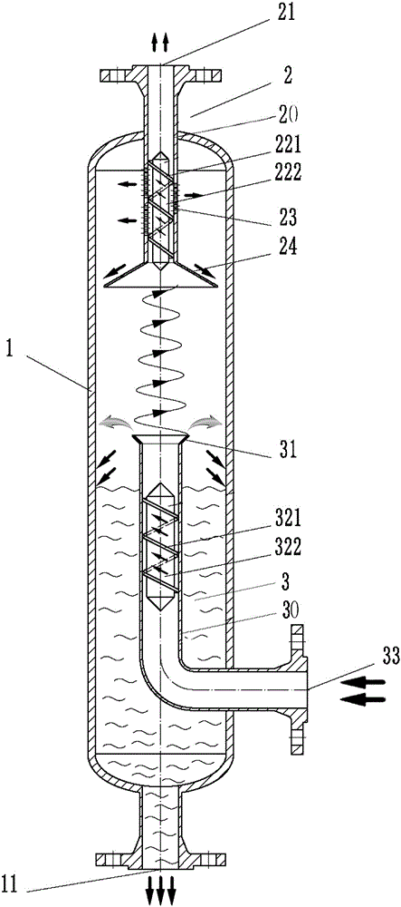
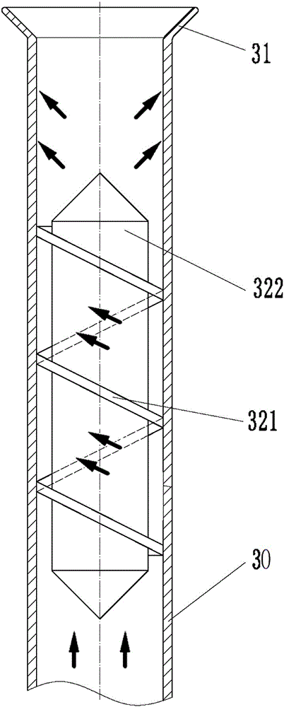
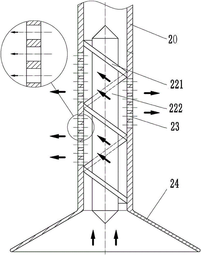
[0027] refer to Figure 1 to Figure 4 , a vortex tube type gas-liquid separator, including a vertical housing 1, a primary spiral separation device 3 and a secondary spiral separation device 2 are installed in the housing 1, and the secondary spiral separation device 2 is located in the Above the primary spiral separation device 3, the lower end of the secondary spiral separation device 2 and the upper end of the primary spiral separation device 3, and the outer wall of the secondary spiral separation device 2 and the outer wall of the primary spiral separation device 3 and the housing 1 There is a certain space between the inner walls. The lower end of the housing 1 is provided with a liquid phase outlet 11; the primary spiral separation device 3 includes a primary centrifugal shell 30, and a primary centrifugal shaft 322 is installed in the primary centrifugal shell 30, and the primary centrifugal shaft 322 is provided with a helical primary vortex blade 321, the lower end ...


PUM

PropertyMeasurementUnit
angleaaaaaaaaaa

Abstract

The invention discloses a vortex tubular gas-liquid separator. The vortex tubular gas-liquid separator comprises a vertical shell, wherein a primary spiral separation device and a secondary spiral separation device are installed in the shell. A two-level centrifugal separation way is adopted, the liquid content of a separated gas phase is reduced to 3 percent or less, the gas content of a liquid phase is reduced to 1 percent or less, so that the metering, sampling and purifying of the gas phase and the liquid phase are guaranteed, the harms of gas-liquid mixed fluid, such as vibration, gas corrosion and corrosion on downstream equipment and pipelines are reduced, and the vortex tubular gas-liquid separator has the advantages of simplicity and compactness in structure, easiness in manufacturing and the like. Under the situations of large and frequent variation of flow and gas-liquid ratio as well as a slug flow, the vortex tubular gas-liquid separator can achieve good gas-liquid separation effects, is widely applicable to various gas-liquid separation fields and particularly suitable for the gas-liquid separation field having high requirements on the separation rate, can achieve a gas-liquid separation effect of a liquid-gas ratio of 1: 100 and can separate a liquid drop with a minimum diameter more than or equal to 5 micrometers.

Description

technical field [0001] The invention relates to a gas-liquid separation device used in petroleum and natural gas industry, chemical industry and environmental protection industry, in particular to a vortex tube type gas-liquid separator. Background technique [0002] In the oil and gas industry, chemical industry, environmental protection industry, etc., a large number of gas-liquid separators are used to separate the liquid in the liquid-containing gas and the gas in the gas-containing liquid. According to the structure, the gas-liquid separator is mainly divided into two types: horizontal gas-liquid separator and vertical gas-liquid separator. [0003] The principle of the horizontal gas-liquid separator is to keep the liquid-containing gas in the cavity for a period of time, and use the gravity of the liquid itself as the driving force to separate the gas-liquid two-phase. It has the advantages of simple structure, large processing capacity, low energy consumption, small ...

Claims


Application Information

Patent Timeline
Patent Type & Authority Applications(China)
IPC IPC(8): B01D45/12
Inventor 胡洪铭张西跃李志飞刘恒
Owner 山东华盛荣油气装备有限公司
Why Eureka
Try Eureka