Pre-rinse unit spray valve mechanism

a technology of spray valve and pre-rinse, which is applied in the direction of mechanical equipment, transportation and packaging, functional valve types, etc., can solve the problems of ejecting water from the valve in spurts, the valve is nearly closed, and the chattering tends to reverberate through, so as to reduce the chattering

Active Publication Date: 2006-12-19
T S BRASS & BRONZE WORKS
View PDF15 Cites 9 Cited by
  • Summary
  • Abstract
  • Description
  • Claims
  • Application Information

AI Technical Summary

Benefits of technology

[0011]It is a principal object of the present invention to provide a spray valve assembly that reduces the chattering typical of conventional spray valves when nearly closed.
[0012]It is another principal object of the present invention to provide a spray valve assembly that includes an integral device for preventing back-flow of dirty water from the sink under certain conditions.
[0013]It is a further principal object of the present invention to provide a spray valve assembly with a spray face that can be changed quickly by manipulation without tools.

Problems solved by technology

A common annoyance with conventional spray valves is a chattering noise and accompanying choppy flow of water that results when the valve is nearly closed.
When the combined forces of the flowing water and the opposing spring in one of these conventional spray valves vibrates the system at the natural frequency of the valve, chatter of the valve results, and water tends to be ejected from the valve in spurts.
Moreover, this chatter tends to reverberate through the connecting pipes that bring the water to the spray valve.
However, the increased force constant imposes an additional force requirement on the user in order to press the valve trigger to open the valve to the flow of water.
Installations that fail to include at the time of installation such a separate back-flow prevention device will suffer from the aforementioned condition at a later date.
The operator's hand can become fatigued from the need to apply constant pressure to maintain the spray valve in the open position.
However, placement of the ring usually requires using both of the operator's hands.
Moreover, during the placement of the ring, the direction of the valve's spray easily can be inadvertently directed where the water is unwanted.
Contact temperatures above 105 degrees Fahrenheit typically would be deemed uncomfortable to the user.
This solution is not effective to prevent the user from coming into contact with the two relatively large metal masses that are disposed on opposite ends of the grip.
The grip portion of conventional spray valves typically is made of relatively brittle plastic that easily can crack if dropped on the edge of a sink for example.
Leaving a broken grip endangers the hand of the user during subsequent use.
This motion-limiting device or the trigger itself is susceptible to damage and one or both often becomes damaged with the passage of time.

Method used


Image

  • Pre-rinse unit spray valve mechanism
  • Pre-rinse unit spray valve mechanism
  • Pre-rinse unit spray valve mechanism

Examples


Embodiment Construction

[0048]Reference now will be made in detail to the presently preferred embodiments of the invention, one or more examples of which are illustrated in the accompanying drawings. Each example is provided by way of explanation of the invention, which is not restricted to the specifics of the examples. In fact, it will be apparent to those skilled in the art that various modifications and variations can be made in the present invention without departing from the scope or spirit of the invention. For instance, features illustrated or described as part of one embodiment, can be used on another embodiment to yield a still further embodiment. Thus, it is intended that the present invention cover such modifications and variations as come within the scope of the appended claims and their equivalents. The same numerals are assigned to the same components throughout the drawings and description.

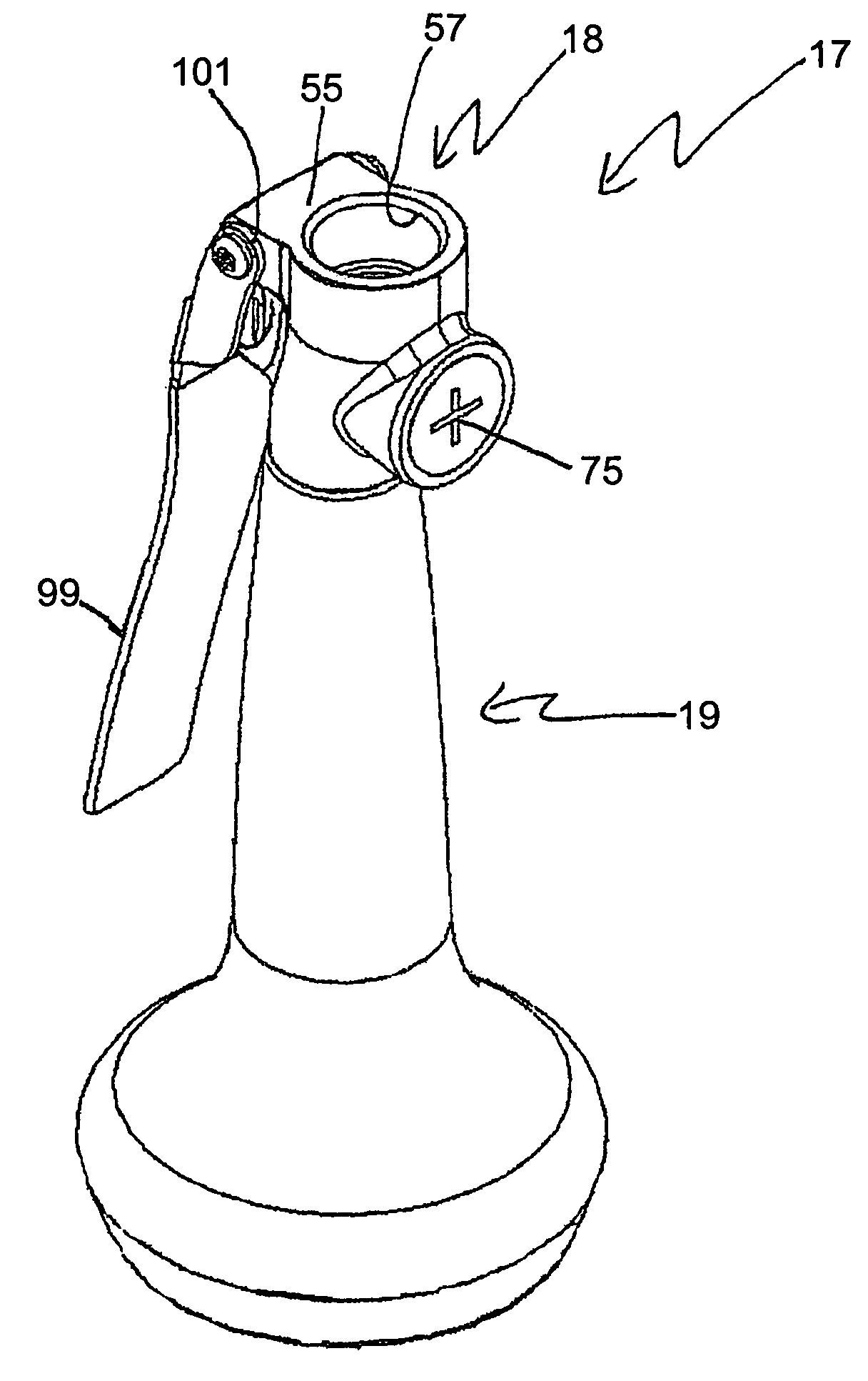
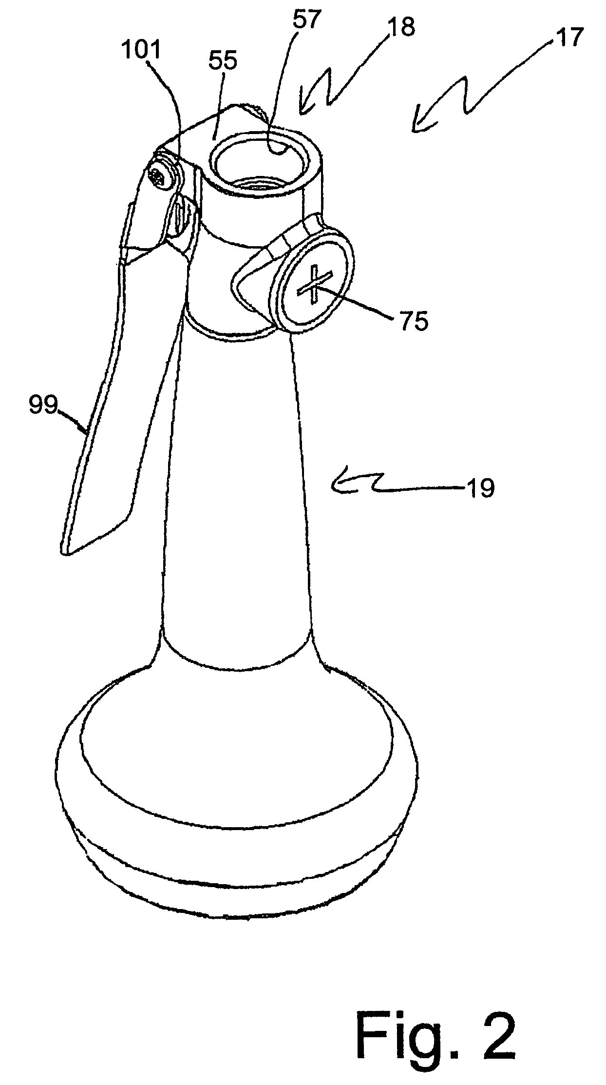
[0049]A presently preferred embodiment of the spray valve of the present invention is shown in an elev...


PUM


Abstract

A spray valve is configured with a fluid path that always provides dynamic water flow on both opposite surfaces of the seating flange of the valve stem when the valve is almost completely closed and when the valve is just beginning to be opened. This equalization of dynamic pressure from the incoming water flow tends to reduce the frequency of vibration that is imposed upon the valve stem and biasing member by the incoming water flow. A check valve is built into the spray valve, which has a trigger lock and a selectively removable spray disk. The valve has an outer sleeve that surrounds the valve's base member and defines a gap therebetween and is formed of mechanical shock-resilient, heat-insulating material.

Description

CROSS-REFERENCE TO RELATED APPLICATIONS[0001]The present application claims priority to currently pending Provisional Patent Application No. 60 / 628,524 filed Nov. 16, 2004.STATEMENT REGARDING FEDERALLY SPONSORED RESEARCH OR DEVELOPEMENT[0002]N / ABACKGROUND OF THE INVENTION[0003]As shown in FIG. 1, a common fixture in a commercial kitchen is a spray valve 10 on the end of a flexible hose 11 that is connected to a vertical riser 12, especially as part of a pre-rinse unit of a dishwasher line. The spray valve 10 has a lever 13 for manual operation to open and close the valve 10. U.S. Pat. Nos. 2,971,520 and 5,624,074 describe a couple of examples. A common annoyance with conventional spray valves is a chattering noise and accompanying choppy flow of water that results when the valve is nearly closed.[0004]Most of the conventional spray valves employ valve springs that bias the valve stem in a direction that is parallel to the flow of water through the valve. In most conventional spray v...

Claims


Application Information

Patent Timeline
Patent Type & Authority Patents(United States)
IPC IPC(8): A62C31/00B05B15/08B05B15/68
CPCB05B1/185B05B1/3013B05B12/002F16K1/38B05B12/0024Y10T137/9464
Inventor WEAVER, MARK V.LANGNER, LUKE EDWARD
Owner T S BRASS & BRONZE WORKS
Why Eureka
Try Eureka