
Display with surface mount emissive elements

a technology of emissive elements and display screens, applied in the field of integrated circuits, can solve the problems of simple driving schemes that are necessarily limited to a relatively small number of rows, and achieve the effects of high reliability, reasonable cost, and large area of high dynamic range display

Active Publication Date: 2017-05-11
ELUX INC
View PDF2 Cites 54 Cited by
  • Summary
  • Abstract
  • Description
  • Claims
  • Application Information

AI Technical Summary

Benefits of technology

This patent describes a new method for creating high dynamic range displays using inorganic micro LEDs. This method allows for the fabrication of large displays with reasonable cost and high reliability. The process involves creating micro LED structures on a sapphire substrate and then depositing them onto a display substrate with well structures. The micro LEDs are then connected to the substrate and powered using a simple or active matrix circuit. The advantages of this method include the ability to control the brightness of each sub-pixel and the use of a more efficient transfer process. However, the cost per pixel can be higher than other methods due to the small size of the micro LEDs and the complex fabrication process.

Problems solved by technology

However, due to sampling and power restraints this simple driving scheme is necessarily limited to a relatively small number of rows.

Method used


Image

  • Display with surface mount emissive elements
  • Display with surface mount emissive elements
  • Display with surface mount emissive elements

Examples


Embodiment Construction

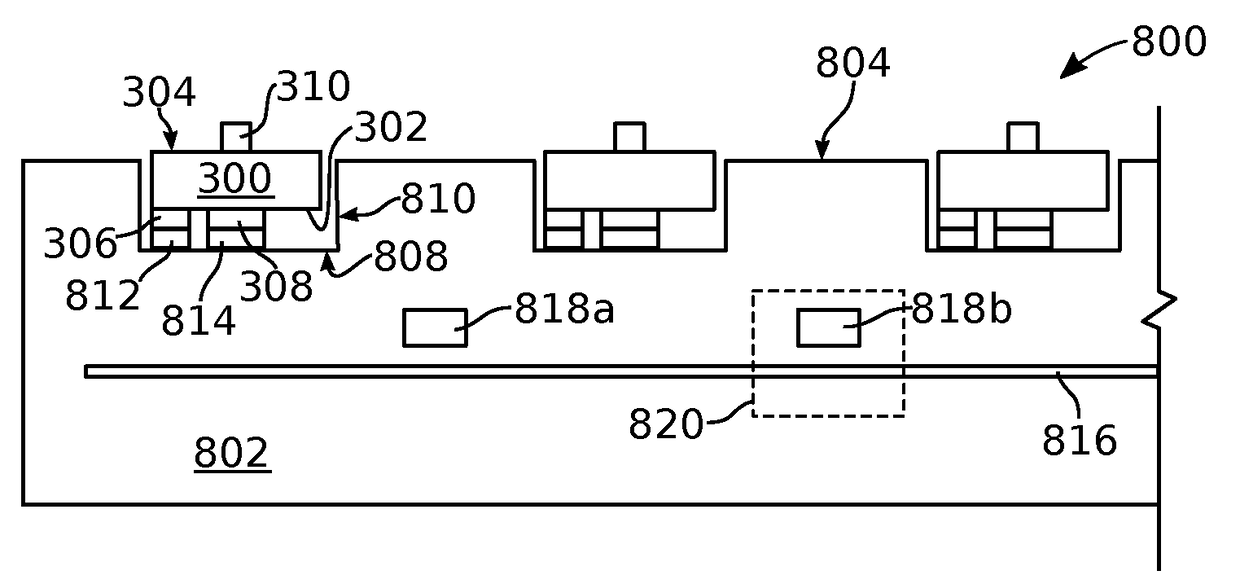
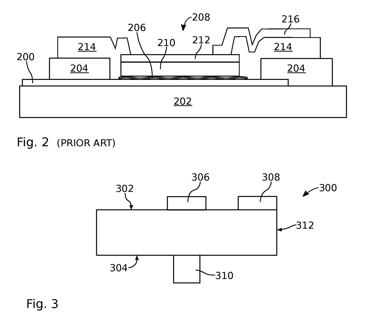
[0058]FIG. 3 is a partial cross-sectional view of a surface mount emissive element. The surface mount emissive element 300 comprises a top surface 302, a bottom surface 304, a first electrical contact 306 formed exclusively on the top surface, and a second electrical contact 308 formed exclusively on the top surface. By “exclusively on the top surface” it is meant that the electrical contacts or electrodes do not extend over the emissive element sides 312 or bottom surface 304. The electrical contacts may be a metal, doped semiconductor, or transparent conductive oxide (TCO) such as indium tin oxide (ITO). Although not explicitly shown as a distinct layer, the electrical contacts 306 and 308 may be solder or solder-coated (e.g., a eutectic solder) for subsequent connection to an emissive substrate. The emissive element 300 further comprises a post 310 extending from the bottom surface 304. In one aspect, the post 310 is centered in the middle of the bottom surface 304. One example o...


PUM


Abstract

A surface mount emissive element is provided with a top surface and a bottom surface. A first electrical contact is formed exclusively on the top surface, and a second electrical contact is formed exclusively on the top surface. A post extends from the bottom surface. An emissive display is also provided made from surface mount emissive elements and an emissions substrate. The emissions substrate has a top surface with a first plurality of wells formed in the emissions substrate top surface. Each well has a bottom surface, sidewalls, a first electrical interface formed on the bottom surface, and a second electrical interface formed on the bottom surface. The emissions substrate also includes a matrix of column and row conductive traces forming a first plurality of column / row intersections, where each column / row intersection is associated with a corresponding well. A first plurality of emissive elements populates the wells.

Description

RELATED APPLICATIONS[0001]This application is a Continuation-in-part of application Ser. No. 14 / 749,569, invented by Sasaki et al., entitled LIGHT EMITTING DEVICE AND FLUIDIC MANUFACTURE THEREOF, filed on Jun. 24, 2015.[0002]This application is a Continuation-in-part of application Ser. No. 15 / 221,571, invented by Crowder et al., entitled SUBSTRATE WITH TOPOLOGICAL FEATURES FOR STEERING FLUIDIC ASSEMBLY LCD DISKS, filed on Jul. 27, 2016.[0003]This application is a Continuation-in-part of application Ser. No. 15 / 197,226, invented by Kurt Ulmer, entitled LAMINATED PRINTED COLOR CONVERSION PHOSPHOR SHEETS, filed on Jun. 29, 2016.[0004]This application is a Continuation-in-part of application Ser. No. 15 / 190,813, invented by Schuele et al., entitled DIODES OFFERING ASYMMETRIC STABILITY DURING FLUIDIC ASSEMBLY, filed on Jun. 23, 2016.[0005]This application is a Continuation-in-part of application Ser. No. 15 / 158,556, invented by Zhan et al., entitled FORMATION AND STRUCTURE OF POST ENHAN...

Claims


Application Information

Patent Timeline
Patent Type & Authority Applications(United States)
IPC IPC(8): H01L33/00H01L33/30H01L25/075H01L33/20H01L33/38H01L33/44H01L33/06H01L25/16
CPCH01L33/0079H01L33/06H01L33/30H01L25/167H01L27/1214H01L33/38H01L33/44H01L25/0753H01L33/32H01L33/20H01L33/62H01L2933/0066H01L33/0093
Inventor SCHUELE, PAUL J.SASAKI, KENJIULMER, KURTLEE, JONG-JAN
Owner ELUX INC
Learn More