Fabric Tube Propulsion Drive

a technology of propulsion drive and fabric tube, which is applied in the field of fabric tube propulsion drive, can solve the problems of high variability in the shape of the area being explored, low traction on the cavitary surface, and numerous challenges of propulsion within the living organism, and achieves high surface area, effective traction, and moderate longitudinal rigidity.

Inactive Publication Date: 2017-05-25
NAGASE DANIEL
View PDF2 Cites 1 Cited by
  • Summary
  • Abstract
  • Description
  • Claims
  • Application Information

AI Technical Summary

Benefits of technology

[0060]1) A flexible tubelike endoskeleton that provides moderate longitudinal rigidity while allowing the device to flex and bend in planes that are perpendicular to it's longitudinal axis. This flexible endoskeleton may be thought of as the internal “frame” of the device.
[0061]2) A continuous loop of elastic fabric or mesh that surrounds both the inner and outer surfaces of the endoskeleton / frame. The fabric or mesh can have various textures to allow for effective traction and propulsion on specific body surfaces. The ideal such surface texture described within this patent is a mesh or fabric surface with “pile” similar to the tufts of “pile” that cover carpet flooring. Such a surface allows for propulsion on slippery surfaces and through liquids by providing a high surface area while on the outside of tubelike body of the device. As the fabric traverses into the inner surface of the tubelike body of the device, the “pile” is compacted producing less surface area and therefore less propulsion opposite to the propulsion forces made on the outside of the device.

Problems solved by technology

However, propulsion within a living organism presents numerous challenges.
First, traction on cavitary surfaces can be low due to the presence of mucus, blood or other fluid.
Third is the high variability in terms of shape of the area being explored.
The multitude of existing and patent proposed propulsion systems have various drawbacks such as complexity, slow movement, or mechanical harm to the organ or body cavity from propulsion system operation.

Method used


Image

  • Fabric Tube Propulsion Drive
  • Fabric Tube Propulsion Drive
  • Fabric Tube Propulsion Drive

Examples


Embodiment Construction

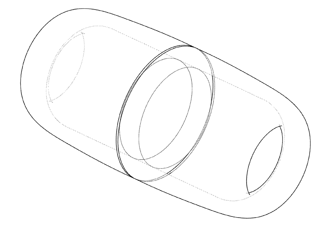
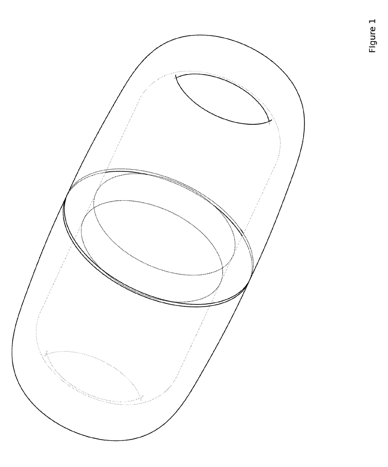
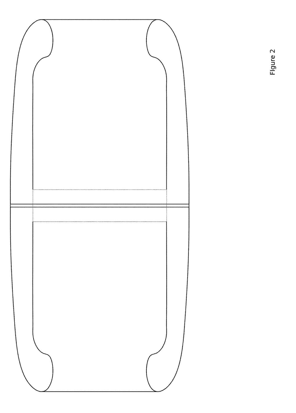
[0069]The figures and following text describe the longitudinally shortest implementation of the Fabric Tube Propulsion Drive. However, variations of the design can easily accommodate any length and width of device necessary to contain video equipment, surgical tools and energy sources to power the system. Alternatively, the drive system may be operated on a tether to obviate the need for an internal power source during endoscopy or laproscopic surgery. A tethered implementation has certain advantages as it can also enable difficult to implement functions in a device that is independent of any connection outside the body, e.g. continuous suction.

[0070]The fabric tube propulsion drive consists of the following components:[0071]1) The endoskeleton: For the Fabric Tube Propulsion Drive, the following physical characteristics must be provided from any specific design implementation of the internal frame of the device, otherwise referred to here on forth as the endoskeleton.[0072]a) The e...


PUM


Abstract

Fabric Tube Propulsion Drive is a system for propelling medical devices through hollow body organs and within body cavities without causing trauma to the body surfaces upon which it operates. Fabric Tube Propulsion Drive consists of a hollow tube surrounded by a continuous loop of elastic fabric or mesh. Within the tube is a motor drive system that moves the fabric through the lumen of the tube such that the fabric on the outside of the tube can continuously interface with the body part through which the Fabric Tube Propulsion Drive is operating, and thereby drive the whole device through the body cavity or over the surface in question. Furthermore, the motor drive system can selectively apply tension to the fabric over specific areas within the tube to cause flexion of the whole tube.

Description

CROSS-REFERENCE TO RELATED APPLICATIONS[0001]U.S. Pat. No. 8,694,092[0002]Ferren, et al. Apr. 8, 2014[0003]Lumen-traveling biological interface device and method of use[0004]U.S. Pat. No. 8,771,175[0005]Schostek, et al. Jul. 8, 2014[0006]Capsule type endoscope including magnetic drive[0007]U.S. Pat. No. 8,328,714[0008]Couvillon, Jr. Dec. 11, 2012[0009]Robotic endoscope[0010]U.S. Pat. No. 8,245,799[0011]Chiel, et al. Aug. 21, 2012[0012]Apparatus and method for locomotion[0013]U.S. Pat. No. 8,214,019[0014]Govari, et al. Jul. 3, 2012[0015]Robotically guided catheter[0016]U.S. Pat. No. 7,857,767[0017]Ferren, et al. Dec. 28, 2010[0018]Lumen-traveling device[0019]U.S. Pat. No. 7,708,687[0020]Bern, et al. May 4, 2010[0021]Endoscope propulsion system and method[0022]U.S. Pat. No. 7,666,135[0023]Couvillon, Jr. Feb. 23, 2010[0024]Robotic endoscope[0025]U.S. Pat. No. 6,988,986[0026]Gross Jan. 24, 2006[0027]Self-propelled imaging system[0028]U.S. Pat. No. 5,337,732[0029]Grundfest, et al. Aug. 1...

Claims


Application Information

Patent Timeline
Patent Type & Authority Applications(United States)
IPC IPC(8): A61B1/00A61B1/018A61B1/04
CPCA61B1/00133A61B1/00137A61B1/018A61B1/04A61B1/00156A61B1/00148
Inventor NAGASE, DANIEL
Owner NAGASE DANIEL
Why Eureka
Try Eureka