
Mismatch Detection Using Replica Circuit

Active Publication Date: 2017-05-25
PSEMI CORP
View PDF43 Cites 30 Cited by
  • Summary
  • Abstract
  • Description
  • Claims
  • Application Information

AI Technical Summary

Benefits of technology

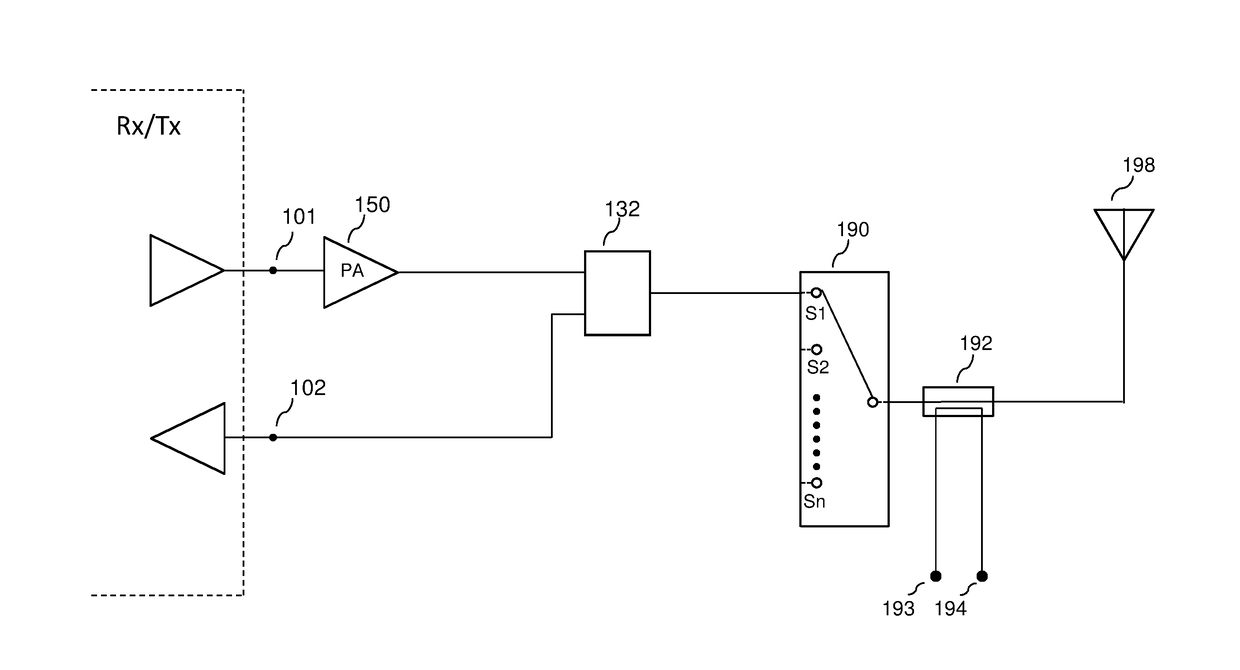
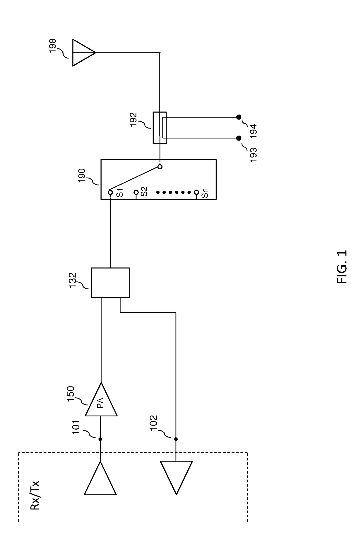
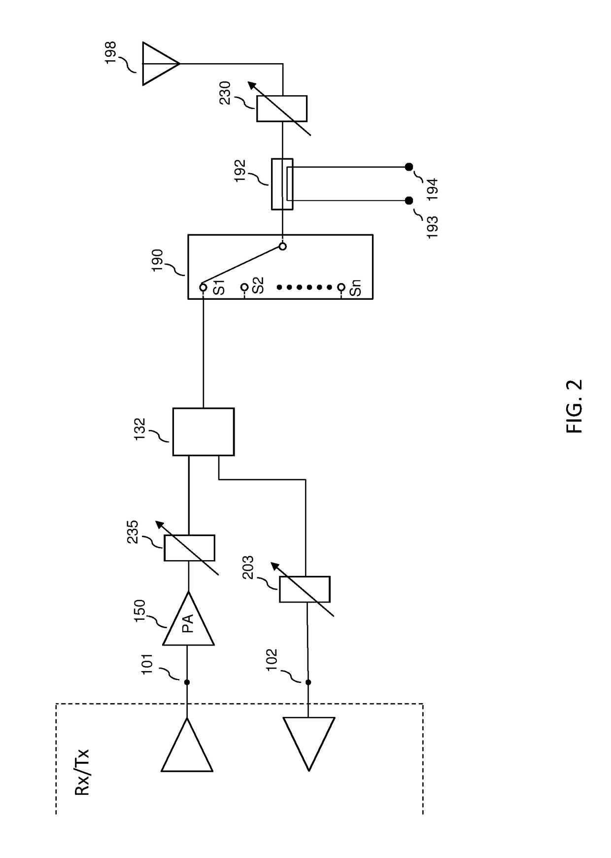
The present disclosure provides a method for using a specific circuital arrangement to compensate for hot carrier injection (HCI) effects on a radio frequency (RF) circuit. The method includes designing a second amplifying circuit that is less stressed and integrating it with the main circuit. By reducing HCI effects on the second amplifying circuit, the method controls biasing to the first amplifying circuit based on a sensed difference in biasing voltages between the two amplifying circuits. This allows for improved performance and reliability of the RF circuit.

Problems solved by technology

In turn, the operating variables can cause performance of the RF circuit to deviate from a nominal performance.
In some cases, it may not be desirable to directly measure performance of the RF circuit during normal operation of the RF circuit, since coupling to the RF circuit for the sake of the measurement may adversely affect performance of the RF circuit.
One may consider measuring the performance during a test mode of the RF circuit with the drawback of not being able to compensate in real time (during normal operation).
Such signals may be influenced by the operating variables in such way that they may not be representative of the real performance of the RF circuit.
As one example, placing the transmitting antenna on a metal table can alter the antenna impedance, causing an impedance mismatch between the power amplifier and the transmitting antenna.

Method used


Image

  • Mismatch Detection Using Replica Circuit
  • Mismatch Detection Using Replica Circuit
  • Mismatch Detection Using Replica Circuit

Examples


Embodiment Construction

[0052]Throughout this description, embodiments and variations are described for the purpose of illustrating uses and implementations of the inventive concept. The illustrative description should be understood as presenting examples of the inventive concept, rather than as limiting the scope of the concept as disclosed herein.

[0053]The term “amplifier” as used in the present disclosure is intended to refer to amplifiers comprising single (e.g. stack height of one) or stacked transistors (e.g. stack height greater than one) configured as amplifiers, and can be used interchangeably with the terms “power amplifier (PA)” and “RF amplifier”. Such terms can refer to a device that is configured to amplify an RF signal input to the device to produce an output RF signal of greater magnitude than the magnitude of the input RF signal. Stacked transistor amplifiers are described for example in U.S. Pat. No. 7,248,120, issued on Jul. 24, 2007, entitled “Stacked Transistor Method and Apparatus”, t...


PUM


Abstract

An apparatus for detecting difference in operating characteristics of a main circuit by using a replica circuit is presented. In one exemplary case, a sensed difference in operating characteristics of the two circuits is used to drive a tuning control loop to minimize the sensed difference. In another exemplary case, several replica circuits of the main circuit are used, where each is isolated from one or more operating variables that affect the operating characteristic of the main circuit. Each replica circuit can be used for sensing a different operating characteristic, or, two replica circuits can be combined to sense a same operating characteristic.

Description

CROSS REFERENCE TO RELATED APPLICATIONS[0001]The present application is a continuation-in-part of U.S. patent application Ser. No. 14 / 883,321 entitled “Mismatch Detection using Replica Circuit”, filed on Oct. 14, 2015, which in turn is a continuation of U.S. patent application Ser. No. 14 / 272,415 entitled “Mismatch Detection using Replica Circuit”, filed on May 7, 2014 and issued as U.S. Pat. No. 9,178,493 on Nov. 3, 2015, the disclosures of all of which are incorporated herein by reference in their entirety.[0002]The present application may be related to U.S. patent application Ser. No. 14 / 272,387 entitled “RF Transmit Path Calibration via On-Chip Dummy Load” filed on May 7, 2014 and published as US Patent Publication No. 2015 / 0326326-A1 on Nov. 12, 2015, the disclosure of which is incorporated herein by reference in its entirety.[0003]The present application may be related to U.S. patent application Ser. No. 13 / 797,779 entitled “Scalable Periphery Tunable Matching Power Amplifier”...

Claims


Application Information

Patent Timeline
IPC IPC(8): G01R31/28H03F3/213H03F3/195H03F1/56
CPCG01R31/28H03F1/56H03F3/213H03F3/195H03F2200/456H03F2200/471H03F2200/102H03F2200/105H03F2200/451H03F2200/387G01R31/2836H03F1/0277H03F1/223H03F1/565H03F3/193H03F3/211H03F3/245H03F3/72H03H7/38H04B1/44H03F2200/378H03F2203/21142H03F2203/7236H04B17/11H04B1/48G01R31/2822G01R31/2856H04B1/006H04B1/0458H04B1/18
Inventor NOBBE, DAN WILLIAMREEDY, RONALD EUGENEBACON, PETERCABLE, JAMES S.
Owner PSEMI CORP
Learn More