
High speed, high precision six degree-of-freedom optical tracker system and method

a tracker system and high-precision technology, applied in the field of optical tracker systems and methods, can solve the problems of heavy, difficult to meet the needs of users, and many existing systems are relatively complex, so as to reduce light noise, improve system accuracy, and minimize the possibility of interference

Active Publication Date: 2017-05-25
HONEYWELL INT INC
View PDF3 Cites 5 Cited by
  • Summary
  • Abstract
  • Description
  • Claims
  • Application Information

AI Technical Summary

Benefits of technology

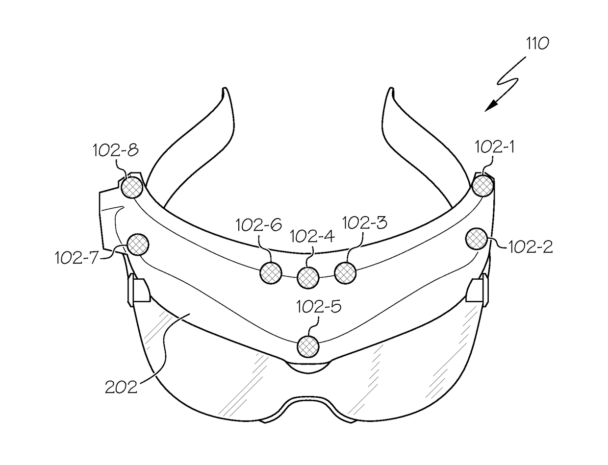
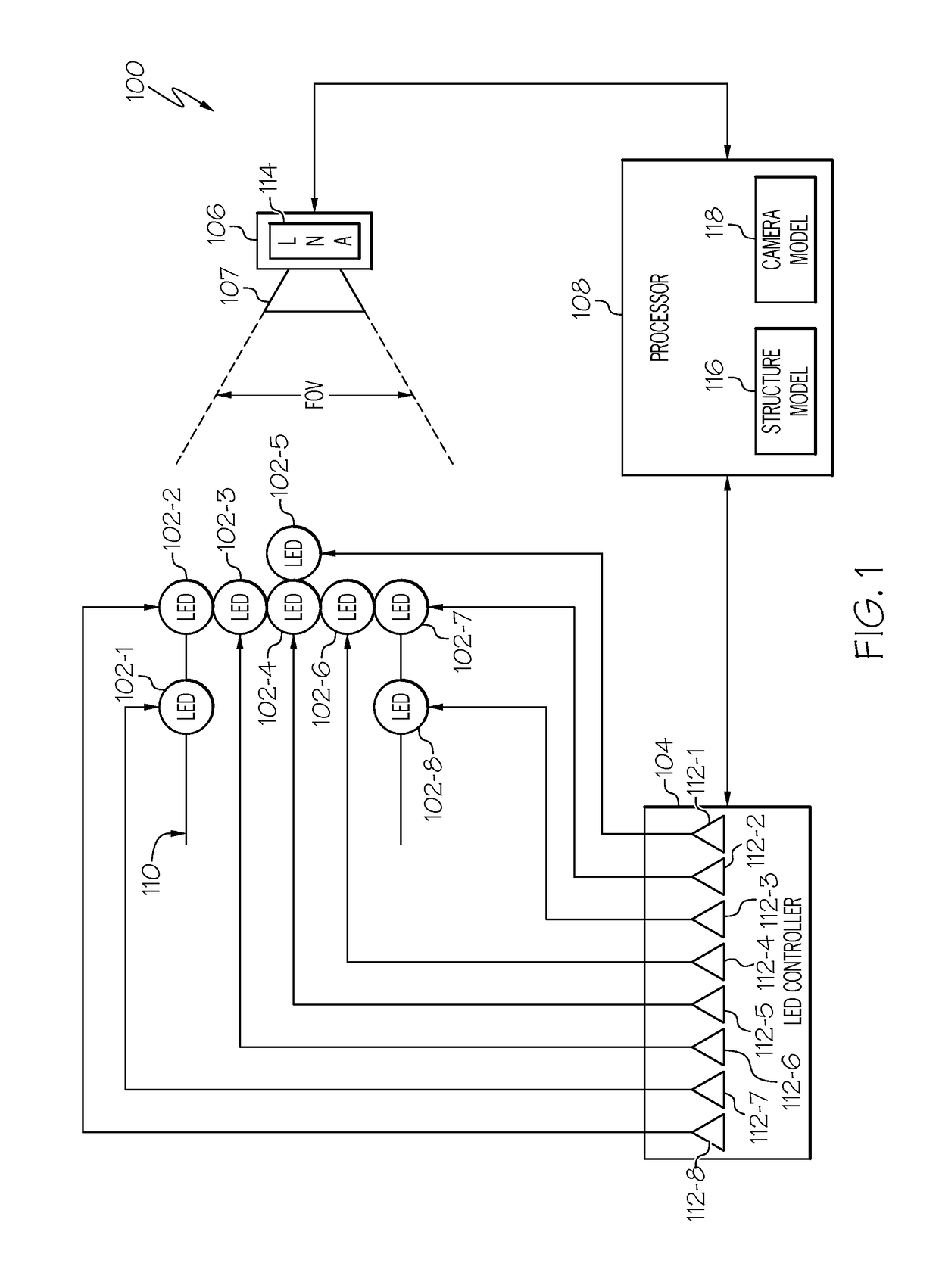
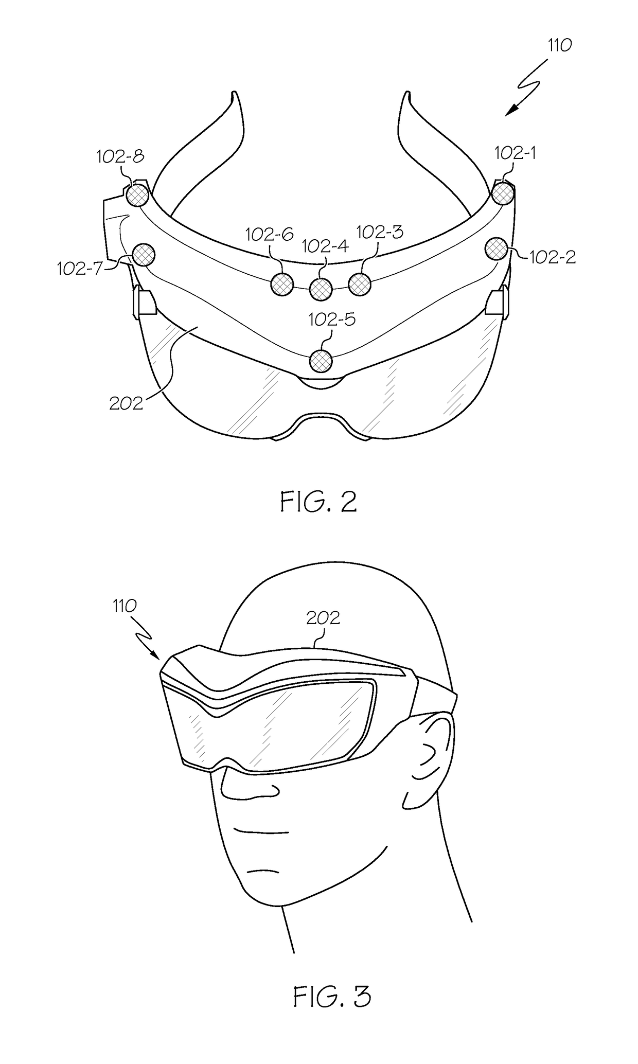
The described optical tracker system uses LEDs mounted on a structure to track the position and orientation of an object. The LEDs are controlled to emit light in a sequential and individual manner, and a position sensing device is used to capture the light emitted from each LED. This data is processed to determine the object's position and orientation relative to the sensing device. The system can detect the position and orientation of the object with high precision, making it useful in various applications such as augmented reality and sports equipment tracking.

Problems solved by technology

Many existing systems are relatively complex, heavy, and expensive.

Method used


Image

  • High speed, high precision six degree-of-freedom optical tracker system and method
  • High speed, high precision six degree-of-freedom optical tracker system and method
  • High speed, high precision six degree-of-freedom optical tracker system and method

Examples


Embodiment Construction

[0020]The following detailed description is merely exemplary in nature and is not intended to limit the invention or the application and uses of the invention. As used herein, the word “exemplary” means “serving as an example, instance, or illustration.” Thus, any embodiment described herein as “exemplary” is not necessarily to be construed as preferred or advantageous over other embodiments. All of the embodiments described herein are exemplary embodiments provided to enable persons skilled in the art to make or use the invention and not to limit the scope of the invention which is defined by the claims. Furthermore, there is no intention to be bound by any expressed or implied theory presented in the preceding technical field, background, brief summary, or the following detailed description.

[0021]In view of the foregoing, although the disclosed systems and methods may be described, in some contexts, as being implemented to track the position and orientation of a user's head for us...


PUM


Abstract

A six degree-of-freedom optical tracker system includes LEDs that are mounted on a structure, and are each configured to emit light. An LED controller is coupled to the LEDs and supplies drive current to each of the LEDs in a manner that causes the LEDs to sequentially and individually emit light. A single position sensing device that is spaced apart from each of the LEDs receives the light emitted from each of the LEDs and supplies position data for each LED. A processor receives the position data and determines the position and orientation of the structure relative to the single position sensing device.

Description

TECHNICAL FIELD[0001]The present invention generally relates to optical tracker systems and methods, and more particularly relates to a high speed, high precision six degree-of-freedom optical tracker system and method.BACKGROUND[0002]In recent years, near-to-eye (NTE) display devices have been developed and are becoming increasingly popular. Depending upon the particular end-use environment, these NTE display devices may be coupled to a helmet or headset of a viewer, and thus move with the changing position and angular orientation of the viewer's head. This advantageously allows the displayed information to be visible to the viewer regardless of the position and / or orientation of viewer's head.[0003]It may thus be appreciated that determining the position and orientation of a viewer's head in six degrees-of-freedom (e.g., x, y, and z, and pitch, yaw, and roll) may be of particular importance to the overall functionality of NTE display devices. Many existing systems are relatively c...

Claims


Application Information

Patent Timeline
IPC IPC(8): G06F3/03F21V23/00G02B27/01F21V19/00G06F3/01H05B37/02H05B33/08H05B44/00
CPCG06F3/0308H05B37/029H05B37/0227F21V23/003F21Y2115/10F21V19/003G06F3/012G02B27/0172H05B33/0854G01S5/16G01S5/163G02B27/0093G06F3/0346H05B47/155H05B47/115Y02B20/40
Inventor MARTINEZ, STEVENERBEN, ERIKRAWSON, MICHAEL
Owner HONEYWELL INT INC
Learn More