A dual operating frequency fiber optic gyroscope

A fiber optic gyroscope, dual-working technology, applied in Sagnac effect gyroscopes, gyroscopes/steering sensing devices, instruments, etc., can solve the problems of difficulty in distinguishing the direction of rotation speed, complex structure of fiber optic gyroscopes, and high optical noise. Simple structure, avoiding interference, reducing optical noise and low effect

Active Publication Date: 2022-01-04
NORTHEAST FORESTRY UNIVERSITY
View PDF10 Cites 0 Cited by
  • Summary
  • Abstract
  • Description
  • Claims
  • Application Information

AI Technical Summary

Problems solved by technology

[0004] Based on the above deficiencies, the present invention provides a dual-working frequency fiber optic gyroscope, wherein the frequencies of the two beams of light waves transmitted in opposite directions are different, which avoids the interference between the two beams of light waves transmitted in opposite directions, and the resonance frequency of the two beams of light waves transmitted in opposite directions At the same time, the magnitude and direction of the rotation speed can be obtained, which overcomes the problems of complex structure, high optical noise and difficulty in distinguishing the direction of rotation speed of the current resonant fiber optic gyroscope.

Method used


Image

  • A dual operating frequency fiber optic gyroscope
  • A dual operating frequency fiber optic gyroscope

Examples


Embodiment 1

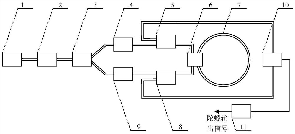
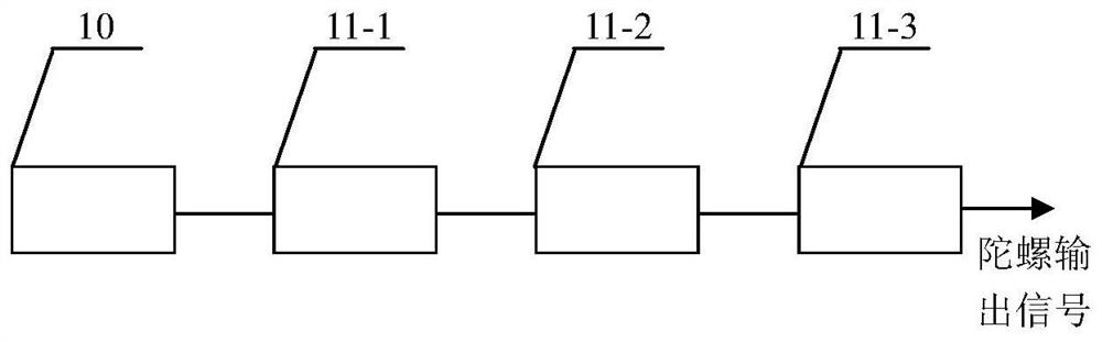
[0022] Such as Figure 1-2 As shown, a fiber optic gyro with dual working frequency includes a light source 1, a polarization controller 2, a fiber beam splitter 3, a first fiber grating 4, a first wavelength division multiplexer 5, a fiber coupler 6, a fiber ring 7, The second wavelength division multiplexer 8, the second fiber grating 9, the spectrometer 10, the signal processing and output system 11, the optical output end of the light source 1 is connected to the optical input end of the polarization controller 2, and the optical output end of the polarization controller 2 is connected to The optical input end of the optical fiber beam splitter 3, the electrical signal output end of the spectrometer 10 are connected to the electrical signal input end of the signal processing and output system 11, and the electrical signal output end of the signal processing and output system 11 outputs the gyro output signal;

[0023] The first optical output end of the optical fiber split...


PUM


Abstract

The invention discloses a dual-working frequency fiber optic gyroscope, comprising a light source, a polarization controller, a fiber beam splitter, a first fiber grating, a first wavelength division multiplexer, a fiber coupler, an optical fiber ring, and a second wavelength division multiplexer device, second fiber grating, spectrometer, signal processing and output system; the first fiber grating and the second fiber grating are narrow-band transmission fiber gratings; the transmission center frequency of the first fiber grating and the second optical fiber The transmission center frequency of the grating is different; the light source is a broadband light source, and its spectral range includes the transmission center frequency of the first fiber grating and the transmission center frequency of the second fiber grating; value, and obtain the size and direction of the fiber optic gyroscope’s rotational speed; the effects and benefits of the present invention are: simple structure, low optical noise, avoiding interference between two beams of light waves transmitted in opposite directions, and without phase modulation of the optical signal. Determine the direction of rotation speed.

Description

technical field [0001] The invention relates to the technical field of fiber optic gyroscopes, in particular to a dual-working frequency fiber optic gyroscope. Background technique [0002] In 1976, V.Vali and R.W.Shorthill of Utah University in the United States successfully developed the first fiber optic gyroscope. As soon as the fiber optic gyroscope came out, it attracted worldwide attention due to its advantages of fast startup, long life, and low power consumption. and has developed rapidly. The fiber optic gyroscope is based on the Sagnac effect, that is, during the transmission of light waves, an additional phase is generated due to the rotation of the relative inertial space. At present, the traditional resonant fiber optic gyroscope uses a fiber optic ring resonator. When the gyroscope rotates, the resonant frequency of the light wave in the fiber optic ring resonator will change with the rotation speed. , the transmission directions of the two are opposite, the...

Claims


Application Information

Patent Timeline
Patent Type & Authority Patents(China)
IPC IPC(8): G01C19/72
CPCG01C19/721G01C19/725
Inventor 崔金刚田赫李景奎
Owner NORTHEAST FORESTRY UNIVERSITY
Why Eureka
Try Eureka