
Methods for indoor 3D surface reconstruction and 2d floor plan recovery utilizing segmentation of building and object elements

a technology of 3d surface reconstruction and floor plan recovery, which is applied in the field of indoor 3d surface reconstruction and 2d floor plan recovery utilizing segmentation of building and object elements, can solve the problems of large number of triangles, inaccurate 3d architectural models of buildings, and 2.5d or 2d floor plans of buildings

Active Publication Date: 2017-05-25
HILTI AG
View PDF5 Cites 24 Cited by
  • Summary
  • Abstract
  • Description
  • Claims
  • Application Information

AI Technical Summary

Benefits of technology

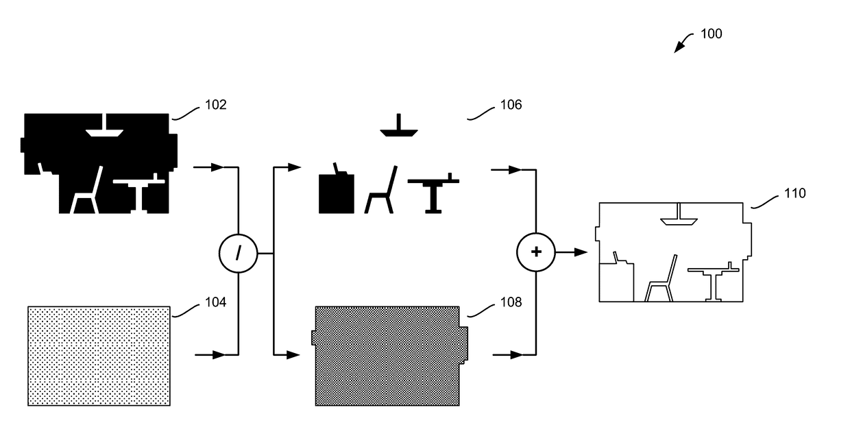
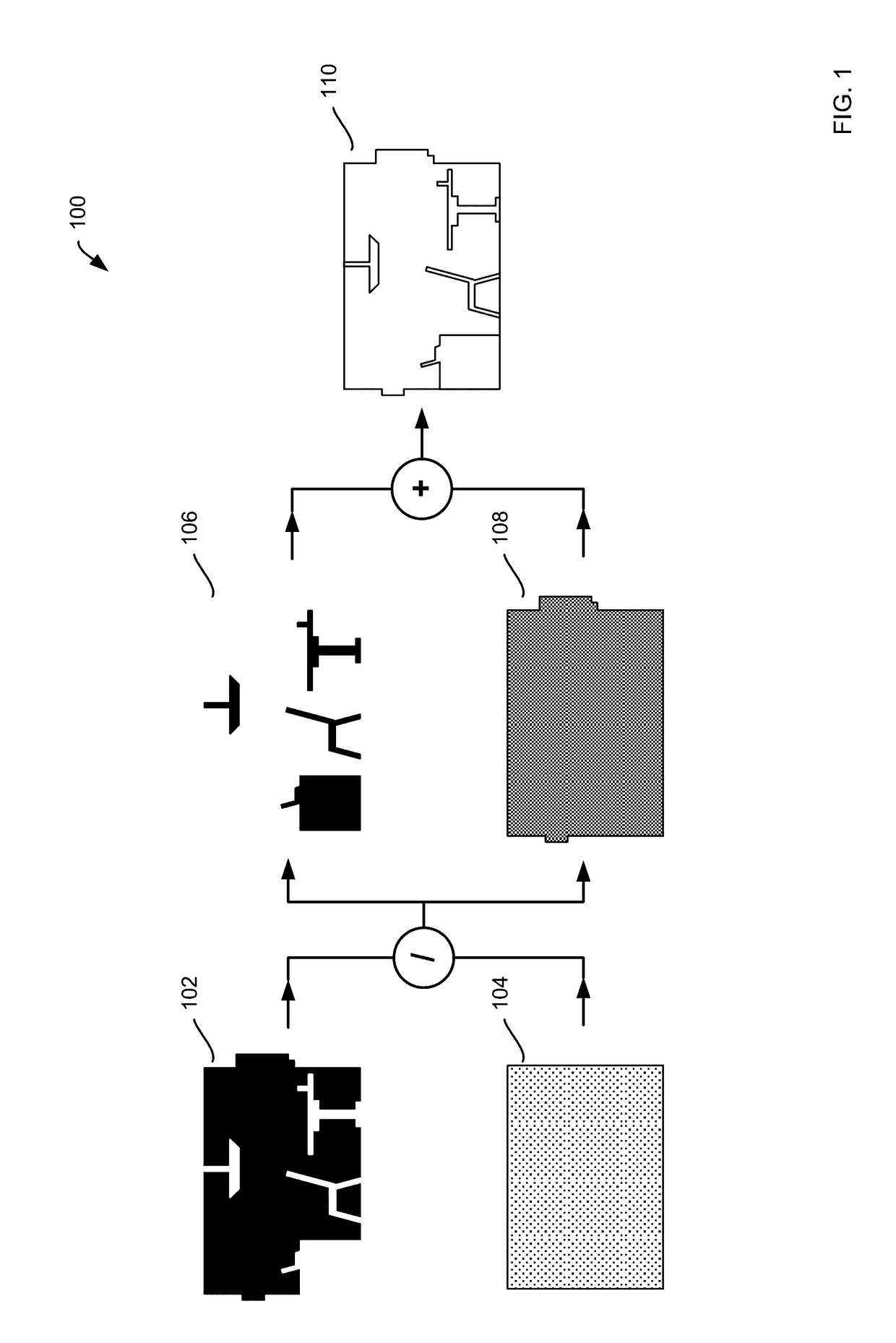
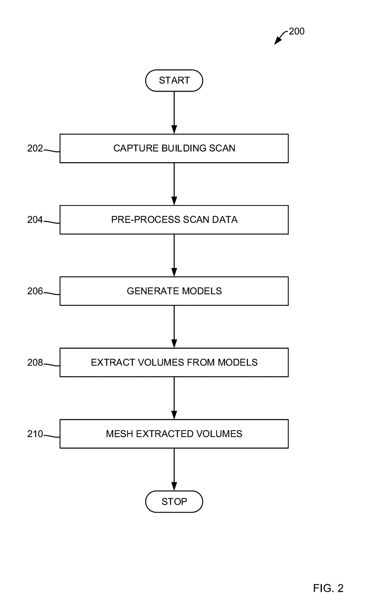
The patent describes a method for reconstructing the interior of a building using a computer scan of the building's structure. The method involves capturing scan data, pre-processing the scan data, and generating an octree and a 2.5D model of the building's structure elements. The scan data is then used to extract interior and exterior volumes, which are used to create a 3D object geometry and a 3D building geometry. The method can be implemented using an electronic computing device and programming software. The technical effects of the invention include improved accuracy in reconstructing the interior of a building and the ability to identify and classify different objects within the building.

Problems solved by technology

Unfortunately, such a single mesh does not faithfully represent the building structure elements due to clutter introduced by objects such as furniture or fixtures and, as such, may result in inaccurate 3D architectural model of the building, or 2.5D or 2D floor plans of the building.
In addition, conventional single mesh algorithms introduce storage and transmission inefficiencies because all elements are represented with the same level of detail resulting in a large number of triangles, even though floors and walls can, in fact, be represented with much fewer trinagles since they are usually planar.

Method used


Image

  • Methods for indoor 3D surface reconstruction and 2d floor plan recovery utilizing segmentation of building and object elements
  • Methods for indoor 3D surface reconstruction and 2d floor plan recovery utilizing segmentation of building and object elements
  • Methods for indoor 3D surface reconstruction and 2d floor plan recovery utilizing segmentation of building and object elements

Examples


Embodiment Construction

[0016]As will be appreciated by one skilled in the art, the present invention may be a system, a method, and / or a computer program product. The computer program product may include a computer readable storage medium (or media) having computer readable program instructions thereon for causing a processor to carry out aspects of the present invention. The computer readable storage medium can be a tangible device that can retain and store instructions for use by an instruction execution device. The computer readable storage medium may be, for example, but is not limited to, an electronic storage device, a magnetic storage device, an optical storage device, an electromagnetic storage device, a semiconductor storage device, or any suitable combination of the foregoing. A non-exhaustive list of more specific examples of the computer readable storage medium includes the following: a portable computer diskette, a hard disk, a random access memory (RAM), a read-only memory (ROM), an erasable...


PUM


Abstract

Methods for indoor 3D surface reconstruction and 2D floor plan recovery by segmenting a number of objects and building structure elements from a building scan using an electronic computing device are presented, the methods including: causing the electronic computing device to capture the building scan, where the building scan includes a number of scan points; pre-processing scan data from the building scan; generating an octree and a 2.5D model from the pre-processed scan data; extracting interior and exterior volumes from the octree model and the 2.5D model; and meshing the extracted volumes to generate a 3D object geometry and a 3D building geometry, where the 3D object geometry corresponds with the number of objects and the 3D building geometry corresponds with the indoor 3D surface reconstruction of building structure elements.

Description

CROSS-REFERENCE TO RELATED APPLICATIONS[0001]The present invention is related to the following applications, all of which are incorporated herein by reference:[0002]Commonly assigned application entitled 3D SPHERICAL IMAGE SYSTEM, U.S. patent application Ser. No. 14 / 855,742, filed on Sep. 16, 2015, by the same inventors herein.BACKGROUND[0003]Augmented and virtual reality, indoor navigation, and building simulation software is rapidly changing. The ability to automatically and rapidly generate a 3D mesh of building surfaces from static or mobile scanning systems is important to many fields, such as augmented and virtual reality, gaming, simulation, architecture, engineering, construction, and emergency response services. Existing 3D meshing algorithms applied to the 3D point cloud of building interiors typically mesh the objects inside the buildings and the building structure elements such as floors, walls, and ceilings together in one mesh. Unfortunately, such a single mesh does no...

Claims


Application Information

Patent Timeline
Patent Type & Authority Applications(United States)
IPC IPC(8): G06T17/05G06T15/00G06V10/147G06V10/44H04N13/243
CPCG06T15/005G06T17/05G06T3/4038G06T17/00G06T15/205G06T15/04H04N13/243G06V10/147G06V10/44H04N23/698G06T3/12G06T19/006H04N13/279H04N25/41
Inventor ZAKHOR, AVIDEHTURNER, ERIC LEE
Owner HILTI AG
Learn More