Method and apparatus for decoupling the power of grid-connected inverter

Active Publication Date: 2017-06-01
DELTA ELECTRONICS SHANGHAI CO LTD +1
View PDF1 Cites 22 Cited by
  • Summary
  • Abstract
  • Description
  • Claims
  • Application Information

AI Technical Summary

Benefits of technology

[0029]This solution accurately computes the coupling amount in real time according to the relationship between active power and reactive power outputted from an inverter, and then decouples the output power according to an amplitude feedforward amount and a phase feedforward amount, respectively, so as to achieve inde

Problems solved by technology

Output power fluctuations generated from grid-connected inverters will decrease the utilization efficiency of the energy, and major fluctuations may cause a shock, or even a safety danger of power grids.
However, the current-controlled grid-connected inverters cannot operate in an island mode.
However, in the prior art both current-controlled and voltage-controlled grid-connected inverters have a problem about the coupling of output power.
That is, the active p

Method used


Image

  • Method and apparatus for decoupling the power of grid-connected inverter
  • Method and apparatus for decoupling the power of grid-connected inverter
  • Method and apparatus for decoupling the power of grid-connected inverter

Examples


Embodiment Construction

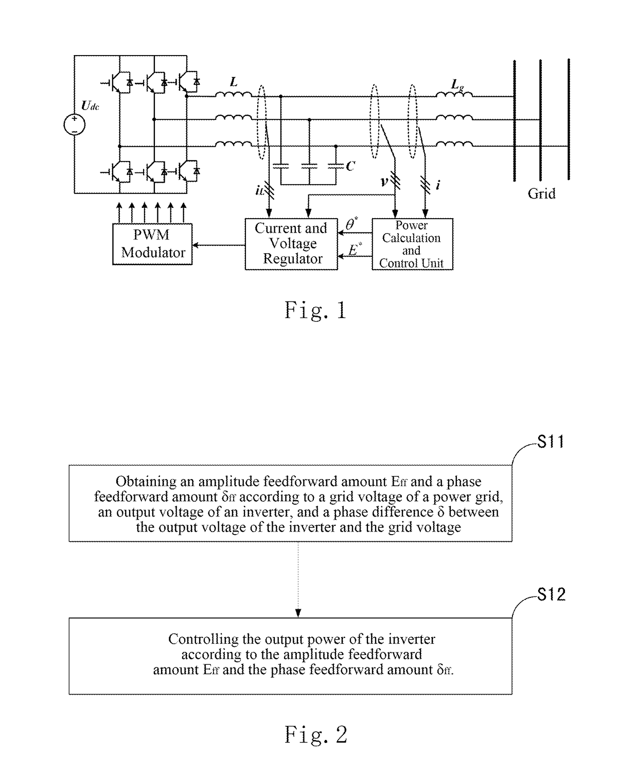
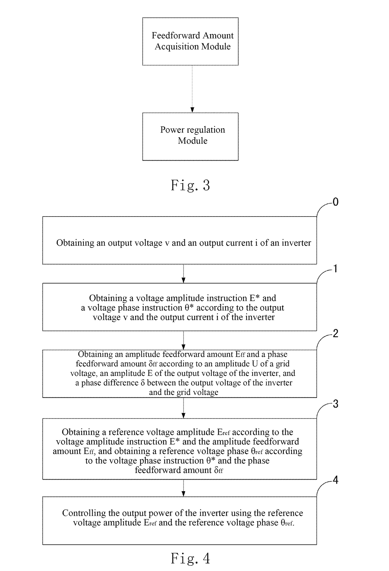
[0042]A preferred embodiment is provided herein to further describe the detailed contents and technical description of the present invention, but should not be construed as limiting the implementation of the present invention.

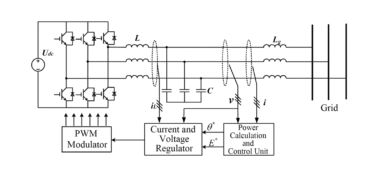
[0043]One embodiment of the present invention provides a technical solution for decoupling the output power of a grid-connected inverter, the principle of which is illustrated in FIGS. 2-8. The results of the comparison between an inverter using this method and an inverter using a conventional control method are shown in FIGS. 9 and 10. FIG. 9A and FIG. 10A show the cases when the instruction for the active power changes. It can be indicated that fluctuations of the reactive power can be effectively suppressed by using the technical solution according to embodiments of the present invention; and FIG. 9B and FIG. 10B show the cases when the instructions for the reactive power changes. It can be inferred that the fluctuations of the active power can be effectivel...


PUM


Abstract

A method and an apparatus for decoupling output power of an inverter are provided. The method comprises: obtaining voltage amplitude instruction E* and voltage phase instruction θ* according to an output voltage and an output current of the inverter; obtaining an amplitude feedforward amount Eff and a phase feedforward amount δff according to an amplitude U of a grid voltage of the power grid, an amplitude E of the output voltage of the inverter, and a phase difference δ between the output voltage of the inverter[0] and the grid voltage; obtaining a reference voltage amplitude Eref according to the voltage amplitude instruction E* and the amplitude feedforward amount Eff, and obtaining a reference voltage phase θref according to the voltage phase instruction θ* and the phase feedforward amount δff; and regulating the output power of the inverter using the reference voltage amplitude Eref and the reference voltage phase θref.

Description

CROSS-REFERENCE TO RELATED APPLICATIONS[0001]This non-provisional application claims priorities under 35 U.S.C. §119(a) on Patent Application No. 201510851797.0 filed in P.R. China on Nov. 27, 2015 and No.201610946590.6 filed in P.R. China on Oct. 26, 2016, the entire contents of which are hereby incorporated by reference.[0002]Some references, if any, which may include patents, patent applications and various publications, may be cited and discussed in the description of this invention. The citation and / or discussion of such references, if any, is provided merely to clarify the description of the present invention and is not an admission that any such reference is “prior art” to the invention described herein. All references listed, cited and / or discussed in this specification are incorporated herein by reference in their entireties and to the same extent as if each reference was individually incorporated by reference.FIELD OF THE DISCLOSURE[0003]The present invention belongs to th...

Claims


Application Information

Patent Timeline
IPC IPC(8): H02J3/18H02M7/537
CPCH02M7/537H02J3/18H02M7/42Y02E40/30H02M1/0093
Inventor LIU, JINJUNLIU, BAOJINLIU, ZENGWU, TENGWANG, SHIKE
Owner DELTA ELECTRONICS SHANGHAI CO LTD
Why Eureka
Try Eureka