
Electrical machine

a technology of electric machines and stators, applied in the direction of dynamo-electric machines, electrical apparatus, magnetic circuit shapes/forms/construction, etc., can solve the problems of reduced efficiency, reduced magnetic properties, and relatively complex stator design, and achieve the effect of reducing manufacturing costs and/or fabrication tolerances, increasing magnetic properties and consequently efficiency

Inactive Publication Date: 2017-06-01
BAUMULLER NURNBERG GMBH
View PDF6 Cites 23 Cited by
  • Summary
  • Abstract
  • Description
  • Claims
  • Application Information

AI Technical Summary

Benefits of technology

The patent aims to provide an improved design for an electrical machine, specifically an axial flux motor, that reduces manufacturing costs and tolerances and increases efficiency by improving magnetic properties. The technical effects include reducing production costs and improving performance of the electrical machine.

Problems solved by technology

In comparison with radial flux motors, which have a number of electrical windings which are arranged perpendicular to the rotation axis and by means of which a magnetic field oriented in the radial direction is provided, the design of the stator is relatively complex, however.
However, the electrical machine provided with a stator of this type has reduced magnetic properties particularly in the low-frequency range, for which reason efficiency is reduced.
Moreover, the mechanical integrity of the stator is relatively low.
Because there always is play during the rolling to form the stator, the individual recesses are not completely aligned, for which reason a cost-intensive post-processing of the stator is necessary for realizing relatively low fabrication tolerances.

Method used


Image

  • Electrical machine
  • Electrical machine
  • Electrical machine

Examples


Embodiment Construction

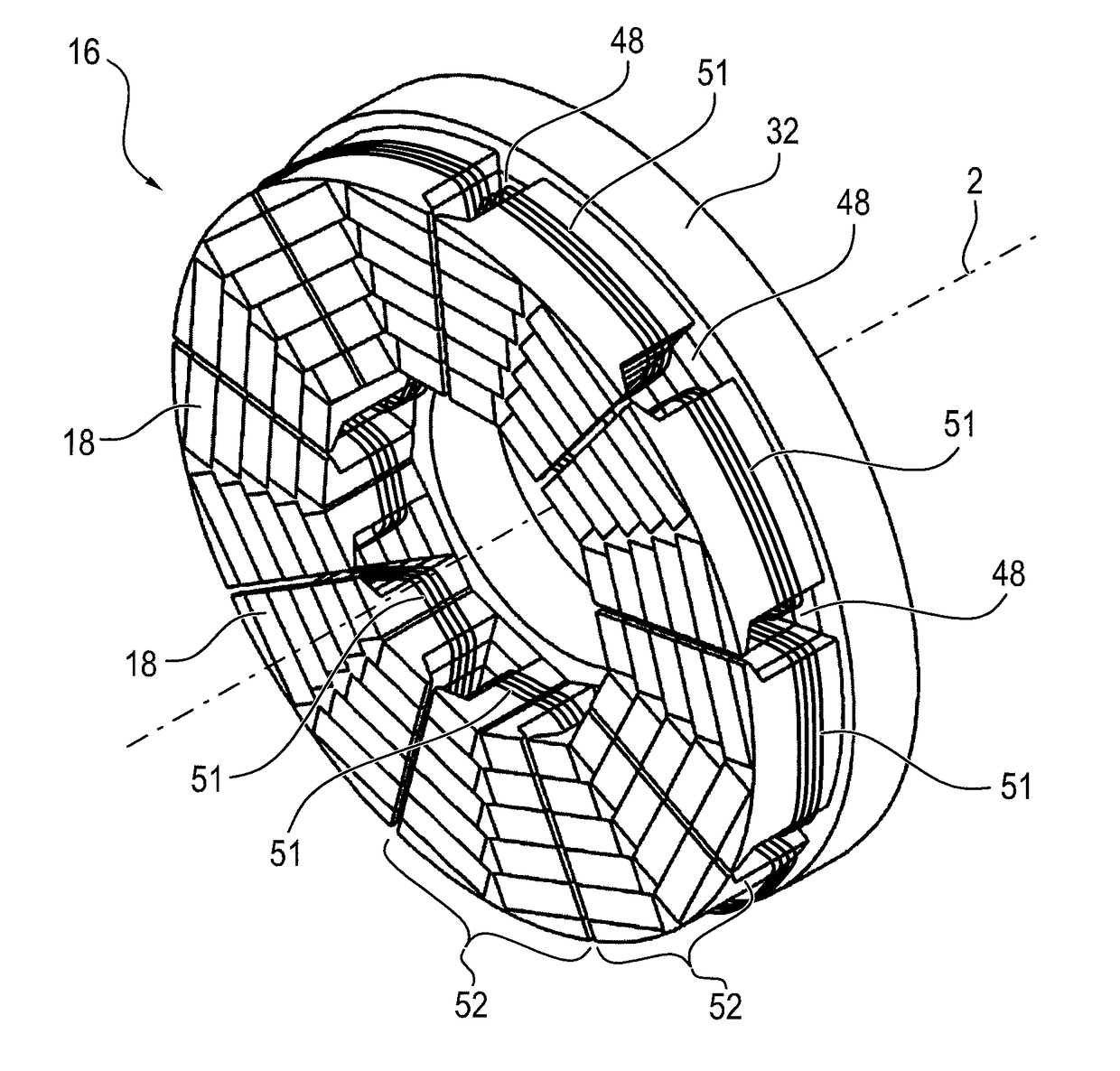
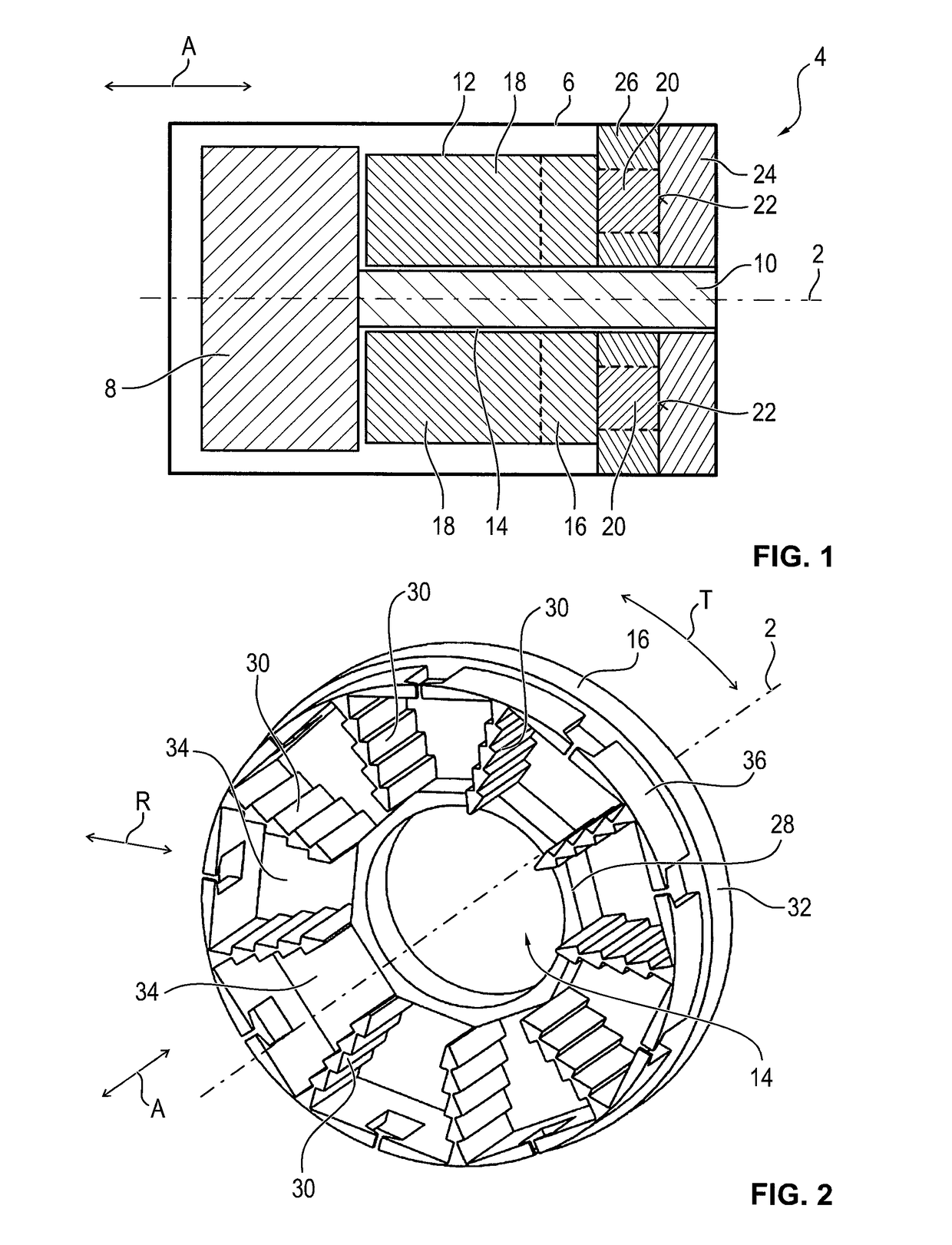
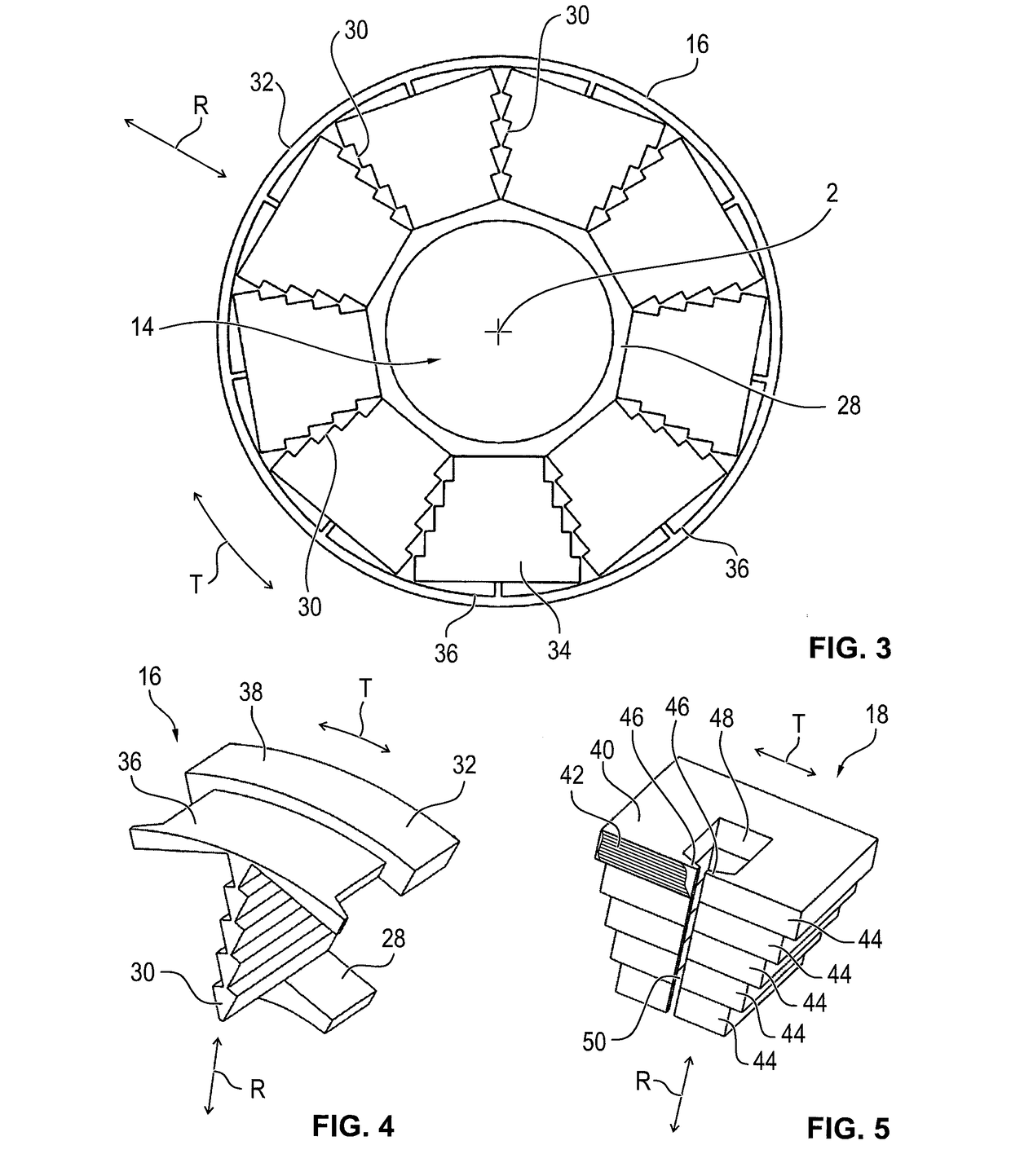
[0050]An electrical machine 4, which is an axial flux motor and which in the assembled state is used for propelling, for example, a motor vehicle, is shown in FIG. 1 in a sectional illustration along a machine axis 2. Electrical machine 4 has a housing 6, within which a rotor 8 is positioned, which is mounted rotatably about machine axis 2 and is connected to a shaft 10. Rotor 8 is designed substantially cylindrical and is disposed concentric to machine axis 2 and to shaft 10. Shaft 10 and rotor 8 are supported by bearings (not shown in greater detail), for example, ball bearings. Shaft 10 is brought out of housing 6, for which the shaft has a journal (not shown in greater detail). Motor vehicle components to be driven, such as a wheel, are connected or at least operatively connected to it.

[0051]Electrical machine 4 further has a stator 12 with a central opening 14, within which shaft 10 is disposed, and which runs parallel to machine axis 2. In other words, stator 12 is designed su...


PUM


Abstract

An electrical machine, in particular an axial flux motor, with a rotor, mounted rotatably about a machine axis, and with a stator. The stator has a sintered support structure and an insert connected thereto, which forms at least partially a pole shoe, and which comprises a lamination stack.

Description

[0001]This nonprovisional application claims priority under 35 U.S.C. §119(a) to German Patent Application No. 10 2015 223 766.4, which was filed in Germany on Nov. 30, 2015, and which is herein incorporated by reference.BACKGROUND OF THE INVENTION[0002]Field of the Invention[0003]The invention relates to an electrical machine with a rotor, mounted rotatably about a machine axis, and with a stator. The electrical machine is in particular an axial flux motor.[0004]Description of the Background Art[0005]Motor vehicles are being increasingly powered by electric motors, which are designed, for example, as wheel hub motors. To increase motor vehicle efficiency and dynamics, it is necessary that the electric motors are designed to be relatively compact and to have a relatively low weight. So-called axial flux motors are particularly suitable for this. These typically have a number of electrical windings, which are arranged parallel to the rotor's rotation axis and around it with the forma...

Claims


Application Information

Patent Timeline
IPC IPC(8): H02K1/18
CPCH02K1/182H02K1/141H02K1/18H02K3/46H02K9/227H02K21/24H02K1/148
Inventor DE K, CSABA ZSOLTKBRAUNEISER, HANS-JUERGENSCHIECK, ROBERTGUTJAHR, FRANK
Owner BAUMULLER NURNBERG GMBH
Learn More