Blade channel, blade cascade and turbomachine

Active Publication Date: 2017-06-08
MTU AERO ENGINES GMBH
View PDF16 Cites 11 Cited by
  • Summary
  • Abstract
  • Description
  • Claims
  • Application Information

AI Technical Summary

Benefits of technology

The present invention provides a blade channel and a blade cascade for a turbomachine that have reduced secondary flows, which enhance the machine's efficiency. The invention achieves this by shaping the side-wall contour of the blade channel to affect the static pressure field and reduce flow losses. The saddle surface, which is located within a specific range, further contributes to the reduction of secondary flows. By incorporating these features, the turbomachine has improved performance relative to machines without the invention.

Problems solved by technology

This leads to vortices and, inter alia, to pressure losses.

Method used


Image

  • Blade channel, blade cascade and turbomachine
  • Blade channel, blade cascade and turbomachine

Examples


Embodiment Construction

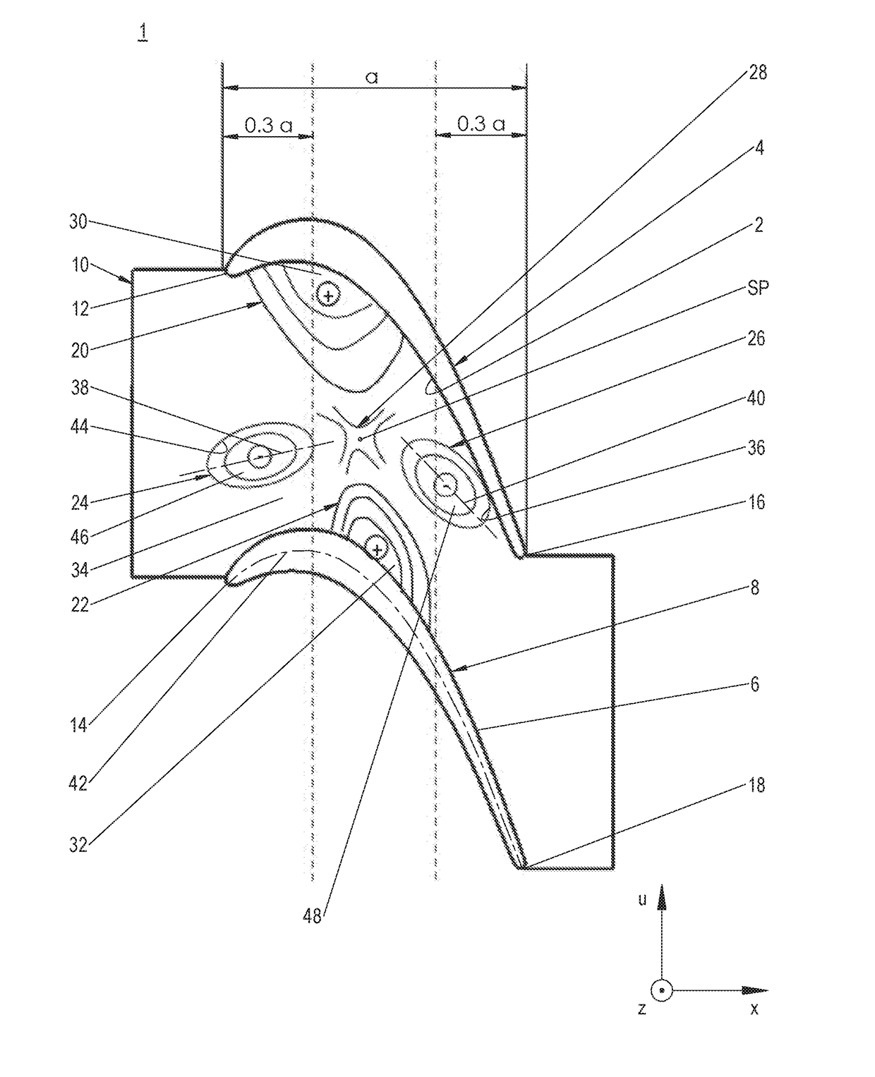
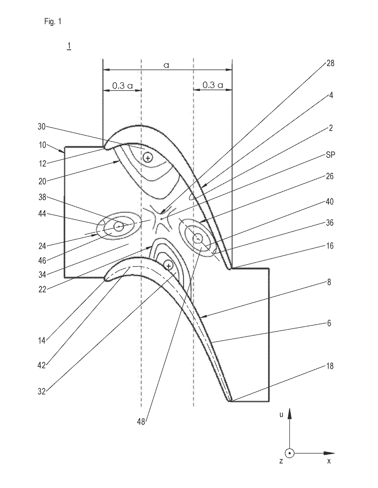
[0022]Blade channel 1 constitutes a portion of a blade cascade of an axial turbomachine, for example. The turbomachine is preferably an aircraft engine, without being limited thereto. For example, the turbomachine may also be a stationary gas turbine or a ship's propulsion. The blade cascade forms a section of an annulus of the turbomachine that is traversed by a primary flow. It is composed of a multiplicity of blade channels 1 that are disposed in circumferential direction u of the turbomachine that are each traversed by a primary flow component. The primary flow components are deflected in blade channels 1 in circumferential direction u, and, altogether, yield the primary flow. The blade cascade is preferably a rotor blade cascade that is optionally located in the area of a low-pressure turbine. Thus, in the exemplary embodiment shown here, the primary flow is a hot gas mixture, which, in simplified terms, flows through the turbomachine in the blade cascade region in axial direct...


PUM


Abstract

A blade channel of a turbomachine that is delimited in the circumferential direction of the turbomachine by a pressure side of an airfoil and by an opposite suction side of an adjacent airfoil that, in the radial direction of the turbomachine, is delimited by two opposing side walls, and whose extent in the axial direction of the turbomachine is delimited by leading edges and by trailing edges of airfoils; at least one of the side walls being provided with localized contours, of which at least two are formed as elevations and at least two as depressions; a saddle surface being formed between the contours that, in one rotation, alternately merges into an elevation and a depression; a blade cascade having such blade channels, as well as a turbomachine having such a blade cascade.

Description

[0001]The present invention relates to a blade channel of a turbomachine, a blade cascade for a turbomachine, and to a turbomachine.BACKGROUND[0002]A fluid flow conveyed through a flow channel is regularly deflected by a lateral pressure gradient parallel to the side walls. Due to the lower velocity thereof, the flow layers proximal to the wall are deflected to a greater degree than the flow layers distal to the wall, thereby forming a secondary flow that is superimposed on a primary flow. This leads to vortices and, inter alia, to pressure losses. The secondary flows regularly occur in blade cascades of turbomachines, such as gas and steam turbines. The blade cascades are composed of a multiplicity of blades or airfoils, which are adjacently disposed in the circumferential direction of the turbomachine and disposed in a rotationally-symmetric flow channel, what is commonly known as an annulus, and between each of which, a blade channel is formed in which the secondary flows are for...

Claims


Application Information

Patent Timeline
IPC IPC(8): F01D5/14B63H21/00F01D5/02B64D27/02
CPCF01D5/145B64D27/02F05D2220/30F01D5/02B63H21/00B63H1/26F01D5/143Y02T50/60
Inventor WOLFRUM, NINABRETTSCHNEIDER, MARKUSMAHLE, INGASCHLEMMER, MARKUSPERNLEITNER, MARTIN
Owner MTU AERO ENGINES GMBH
Why Eureka
Try Eureka