
Bone conduction speaker

a speaker and bone technology, applied in the field of bone conduction speakers, can solve the problems of difficult to raise the sound quality of music, etc., and achieve the effects of improving the frequency characteristics of music, high sound quality, and communication at a good voice level

Inactive Publication Date: 2017-06-08
TEMCO JAPAN
View PDF6 Cites 15 Cited by
  • Summary
  • Abstract
  • Description
  • Claims
  • Application Information

AI Technical Summary

Benefits of technology

The bone conduction earphone described in this patent has a unique design that allows it to produce a voice sound through a person's bones. It also has a separate space inside the housing that creates a "respiratory tract sound" which is helpful for hearing non-impaired people. This earphone can be used for both listening to music and making phone calls, and it always provides high-quality sound.

Problems solved by technology

However, in the latter case of usage, there is no problem for communications at a voice level, but the transmission characteristics of bone vibration involves a great attenuation at a high-area side, and thus in listening to music, it is difficult to raise the sound quality of the music.
As described above, in the case where a hearing non-impaired person uses a bone conduction speaker, there has been a problem that the transmission characteristics of bone vibration involves a great attenuation at a high-area side, and thus in listening to a music, it is difficult to raise the sound quality of the music.

Method used


Image

  • Bone conduction speaker
  • Bone conduction speaker
  • Bone conduction speaker

Examples


Embodiment Construction

[0024]Hereinbelow, an embodiment of the present invention will be explained with reference to the attached drawings.

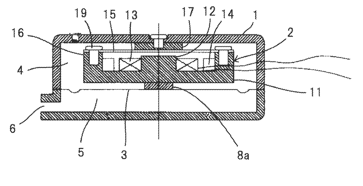
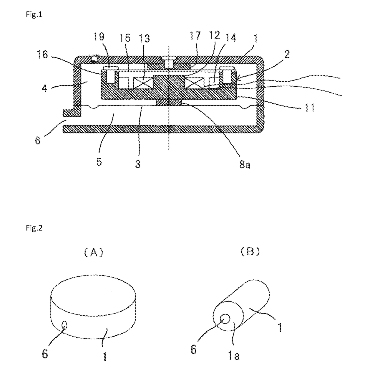
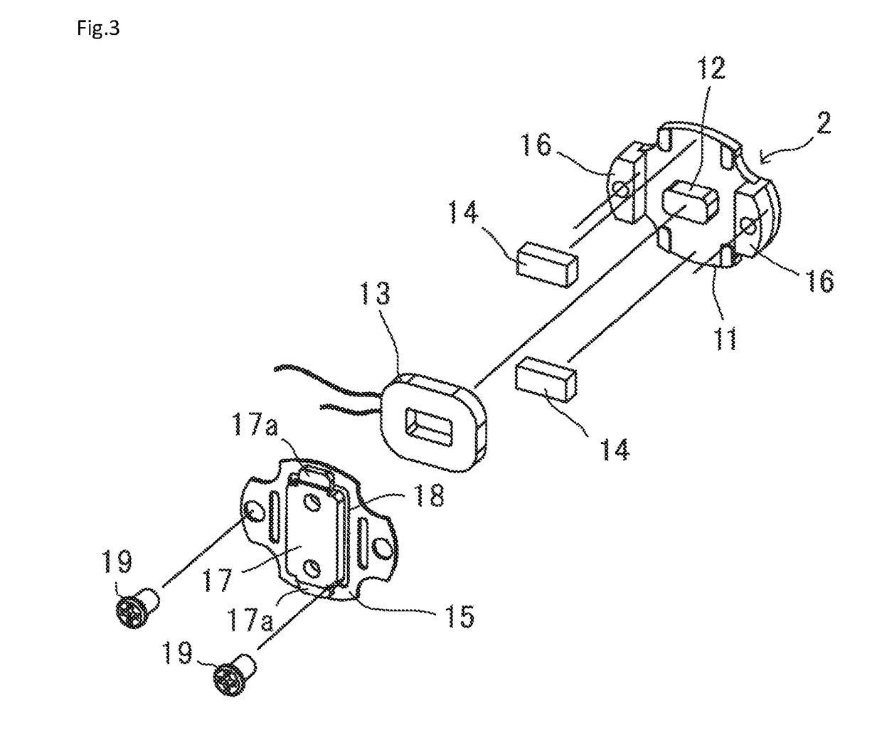
[0025]FIG. 1 is a longitudinal sectional view of a bone conduction speaker according to one embodiment of the present invention, and as shown in the same figure, the bone conduction speaker includes a housing 1; a bone conduction speaker unit 2 incorporated in the housing 1; and a second diaphragm 3 fixed on a bottom face of the bone conduction speaker unit 2. In addition, with a peripheral part of the second diaphragm 3 being fixed to an inner surface of the housing 1 over its entire periphery, an upper air chamber 4 is formed on the upper side of the second diaphragm 3, while, on the lower side of the second diaphragm 3, a lower air chamber 5 is formed, and in a side face or bottom face of the lower air chamber 5, a sound emitting port 6 that opens toward the outside is formed.

[0026]The bone conduction speaker unit 2 used in embodiments of the present invention is co...


PUM


Abstract

Problem: To provide a bone conduction speaker that, while it is a bone conduction speaker, additionally has a structure allowing a respiratory tract sound to be generated, thereby the high frequency characteristics thereof being improved, and thus, that, in the case where it is used by a hearing non-impaired person, communications at a good voice level can be made as well as in the case where it is used by a hearing impaired person, and further, when the hearing non-impaired person uses it to listen to a music, the music can be enjoyed with a high sound quality.Solution: A second diaphragm 3 is fixed to a bottom face of a bone conduction speaker unit 2 incorporated in a housing 1; a peripheral part of the second diaphragm 3 is fixed to an inner surface of the housing 1 over its entire periphery, thereby an upper air chamber 4 being formed on the upper side of the second diaphragm 3, and a lower air chamber being formed on the lower side thereof; and a sound emitting port 6 is formed in a side face or a bottom face of the lower air chamber 5.

Description

CROSS-REFERENCE TO RELATED APPLICATIONS[0001]This application claims priority to PCT Application No. PCT / JP2015 / 061079, having a filing date of Apr. 9, 2015, based on JP 2014-131066, having a filing date of Jun. 26, 2014, the entire contents of which are hereby incorporated by reference.FIELD OF TECHNOLOGY[0002]The following relates to a bone conduction speaker, and more particularly, relates to a bone conduction speaker which, in consideration of that it may be used by a hearing non-impaired person, allows generation of not only a bone conduction sound, but also a respiratory tract sound.BACKGROUND[0003]The bone conduction speaker generally has a structure with which a vibrating surface of a vibrating member of the bone conduction speaker unit is abutted against an internal surface of a housing, being fixed thereto, thereby the entire housing being vibrated, and the general way of using it is to apply a vibrating surface of the housing to the nipple-like protruded portion, or the l...

Claims


Application Information

Patent Timeline
Patent Type & Authority Applications(United States)
IPC IPC(8): H04R1/10H04R25/00H04R1/46H04R9/06
CPCH04R1/1008H04R9/06H04R2460/13H04R25/48H04R1/46H04R1/1016H04R7/04H04R25/606H04R1/24H04R1/345
Inventor FUKUDA, MIKIO
Owner TEMCO JAPAN
Learn More