Motor and a hair care appliance comprising a motor

a hair care appliance and motor technology, applied in the direction of machines/engines, mechanical equipment, liquid fuel engines, etc., can solve the problems of reducing the size of the motor, affecting the operation of the hair care appliance, etc., to achieve the effect of reducing the associated pressure loss, facilitating the passage of the remainder, and being more able to handl

Active Publication Date: 2017-06-15
DYSON TECH LTD
View PDF15 Cites 5 Cited by
  • Summary
  • Abstract
  • Description
  • Claims
  • Application Information

AI Technical Summary

Benefits of technology

[0007]As a result the one or more grooves provide a channel through which foreign objects such as strands of hair are able to pass the impeller blades. Alternatively, part of the hair strand may enter the groove whilst the rest of the strand gets chopped off by an impeller blade as it passes. This process may repeat such that a long strand of hair becomes chopped up into small, more manageable pieces. Therefore foreign objects and hair strands are less susceptible to becoming entangled with the impeller and other rotating parts of the motor. The motor is therefore better able at handling the ingress of foreign objects, and a greater level of reliability for the motor and also the overall appliance is achieved.
[0015]The diffuser portion of the frame may comprise a plurality of diffuser vanes. The frame may comprise a substantially cylindrical inner wall which is concentric to the outer wall and positioned radially within the outer wall, and the plurality of diffuser vanes may extend between the inner wall and the outer wall of the frame. As a result, the inner and outer walls define a diffuser channel through which the generated airflow passes, and no separate diffuser is required in addition to the frame. By reducing the number of motor components in this way, the cost of the motor can be reduced, and in turn the cost of the appliance will be reduced.

Problems solved by technology

However, reducing the size of the motor has its own limitations.
Furthermore, in general the smaller a motor is the more susceptible it becomes to the ingress of foreign objects such as dust and hair into the motor.
In hair care appliances, ingress of loose hair can be particularly problematic.
If strands of hair become wrapped around or entangled with moving parts of the motor, this can have a detrimental effect on the performance of the motor and therefore the entire hair care appliance.
In extreme circumstances, the ingress of foreign objects such as hair into the motor could lead to faults occurring or even failure of the motor entirely.

Method used


Image

  • Motor and a hair care appliance comprising a motor
  • Motor and a hair care appliance comprising a motor
  • Motor and a hair care appliance comprising a motor

Examples


Embodiment Construction

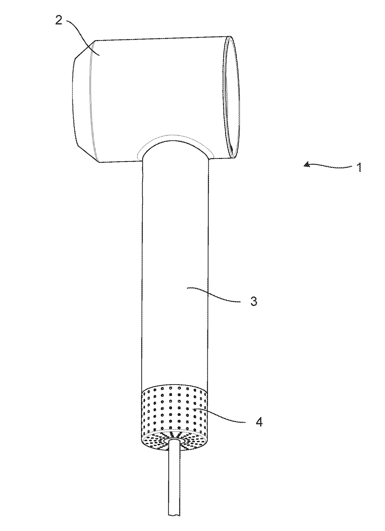
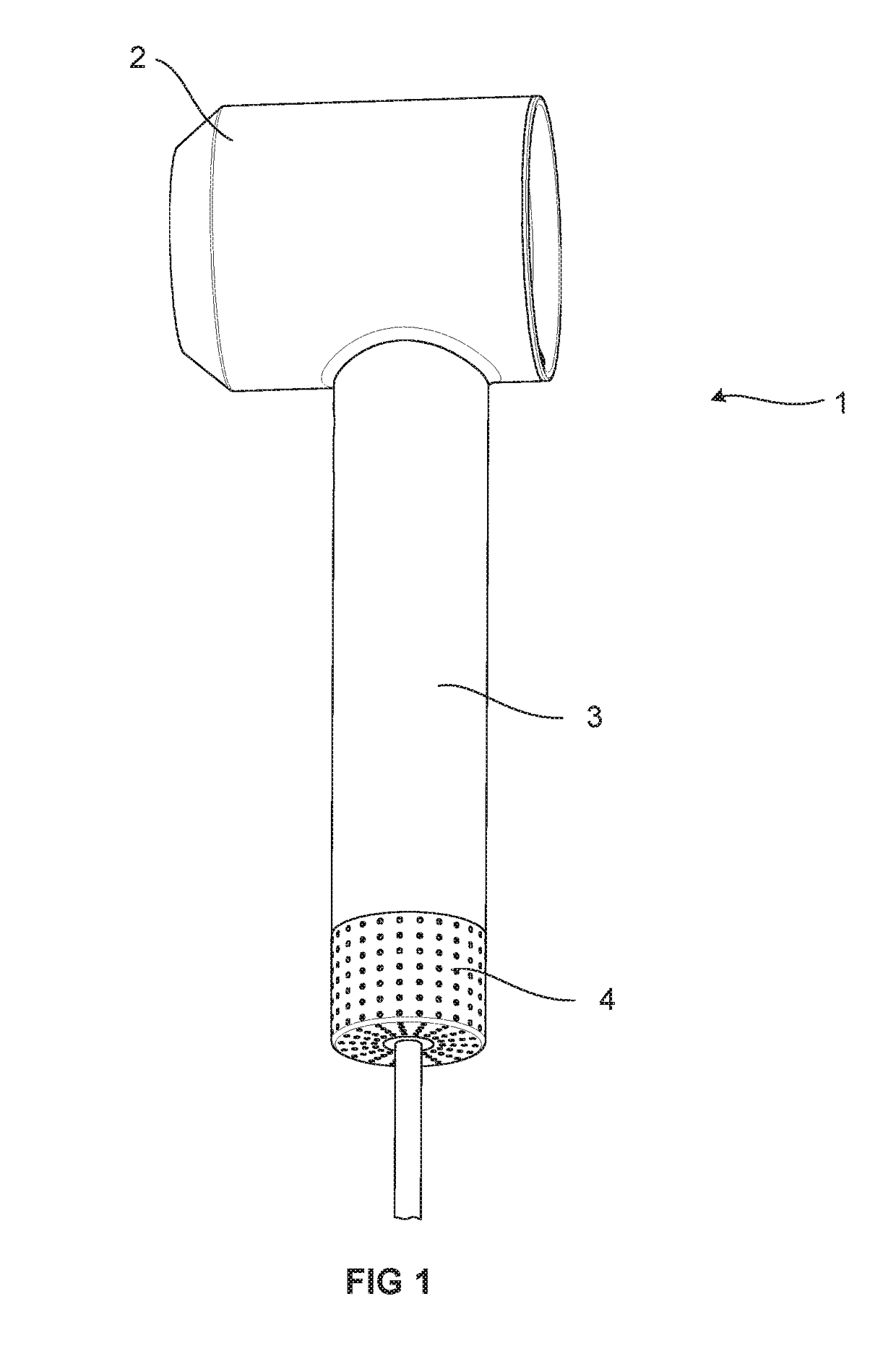
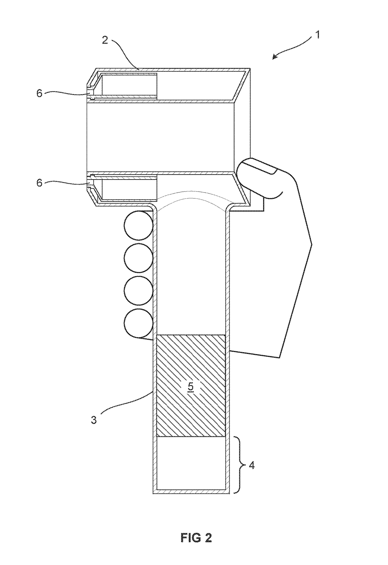
[0027]FIGS. 1 and 2 show a hair care appliance, represented by hair dryer 1. FIG. 2 is a schematic illustration of a cross section through the hair dryer 1. The hair dryer 1 has a body 2 through which air is expelled, and a handle 3 attached to the body 2by which a user can hold the hair dryer 1 as shown in FIG. 2. The handle 3 comprises an air intake 4 at an end of the handle 3 opposite the body 2. A motor 5 is located within the handle 3 such that it is positioned next to, or at least close to, the air intake 4. A filter or other filtering means (not shown) may be provided at the air intake 4, or between the air intake 4 and the motor 5, to prevent foreign objects which may be entrained in the airflow, such as hair or dust, from entering the motor 5.

[0028]During use, the motor 5 generates an airflow through the hair dryer 1. The motor 5 draws air into the handle 3 through the air intake 4. Air then passes through the motor 5 and from the handle 3 into the body 2 where is directed ...


PUM


Abstract

A hair care appliance including a motor for generating an airflow through the appliance, the motor comprising: a frame for supporting a rotor assembly, the frame including an outer wall; and a rotor assembly including a shaft and an impeller, the impeller including a plurality of blades. An impeller housing portion of the outer wall surrounds the impeller. An inner surface of the impeller housing portion includes at least one groove extending in an axial direction and positioned such that the at least one groove extends along at least the axial extent of the blades of the impeller.

Description

REFERENCE TO RELATED APPLICATIONS[0001]This application claims the priority of United Kingdom Application No. 1521889.4, filed Dec. 11, 2015, the entire contents of which are incorporated herein by reference.FIELD OF THE INVENTION[0002]The present invention relates to a hair care appliance comprising a motor.BACKGROUND OF THE INVENTION[0003]Hair care appliances which generate an airflow, for example hair dryers or hot styling brushes, need motors to generate the airflow through them. A number of considerations must be taken with respect to the overall appliance. For instance, the size and weight of the appliance must be kept down in order that a user is able to handle the appliance easily, and that the appliance does not cause discomfort to the user during use.[0004]In hair care appliances it is often the motor that contributes the most towards the size and weight of the overall appliance, and therefore it is important to minimise the size and weight of the motor as much as possible...

Claims


Application Information

Patent Timeline
Patent Type & Authority Applications(United States)
IPC IPC(8): A45D20/12A45D20/50
CPCA45D20/12A45D20/50A45D20/10F04D25/084F04D29/325F04D29/38H02K5/22H02K7/14H02K7/145H02K2205/00
Inventor WARNE, DAVID GEORGE
Owner DYSON TECH LTD
Why Eureka
Try Eureka