Pivotal connection for heavy-duty vehicle suspension assembly

a suspension assembly and pivotal connection technology, which is applied in the direction of screws, threaded fasteners, bolts, etc., can solve the problems of less than the optimal pivotal connection and affecting the safety of the suspension assembly

Active Publication Date: 2017-06-15
HENDRICKSON USA L L C
View PDF2 Cites 5 Cited by
  • Summary
  • Abstract
  • Description
  • Claims
  • Application Information

AI Technical Summary

Benefits of technology

[0011]One aspect of the disclosed subject matter is to provide a pivotal connection for an axle / suspension system of a heavy-duty vehicle that enables economical secure clamping engagement to be formed between a bushing assembly of each suspension assembly and its respective hanger to overcome any adverse effects of a protective medium on the hanger.

Problems solved by technology

It has been found that the coated outboard and inboard surfaces of the hanger walls have a relatively low coefficient of friction, thereby inhibiting the secure clamping engagement between the hanger and the bushing assembly, and in turn providing less than an optimal pivotal connection for the suspension assembly to its respective hanger.
However, the painting-and-masking technique / process is undesirably time-consuming and costly.
It has been found that the coated outboard and inboard surfaces of the hanger walls have a relatively low coefficient of friction, thereby inhibiting the secure clamping engagement between the hanger and the bushing assembly, and in turn providing less than an optimal pivotal connection for the suspension assembly to its respective hanger.
This attempt was found to be insufficient for paint coated hanger walls to provide the sufficient clamping engagement between the hanger and the bushing assembly, and in turn provided less than an optimal pivotal connection for the suspension assembly to its respective hanger.

Method used


Image

  • Pivotal connection for heavy-duty vehicle suspension assembly
  • Pivotal connection for heavy-duty vehicle suspension assembly
  • Pivotal connection for heavy-duty vehicle suspension assembly

Examples


Embodiment Construction

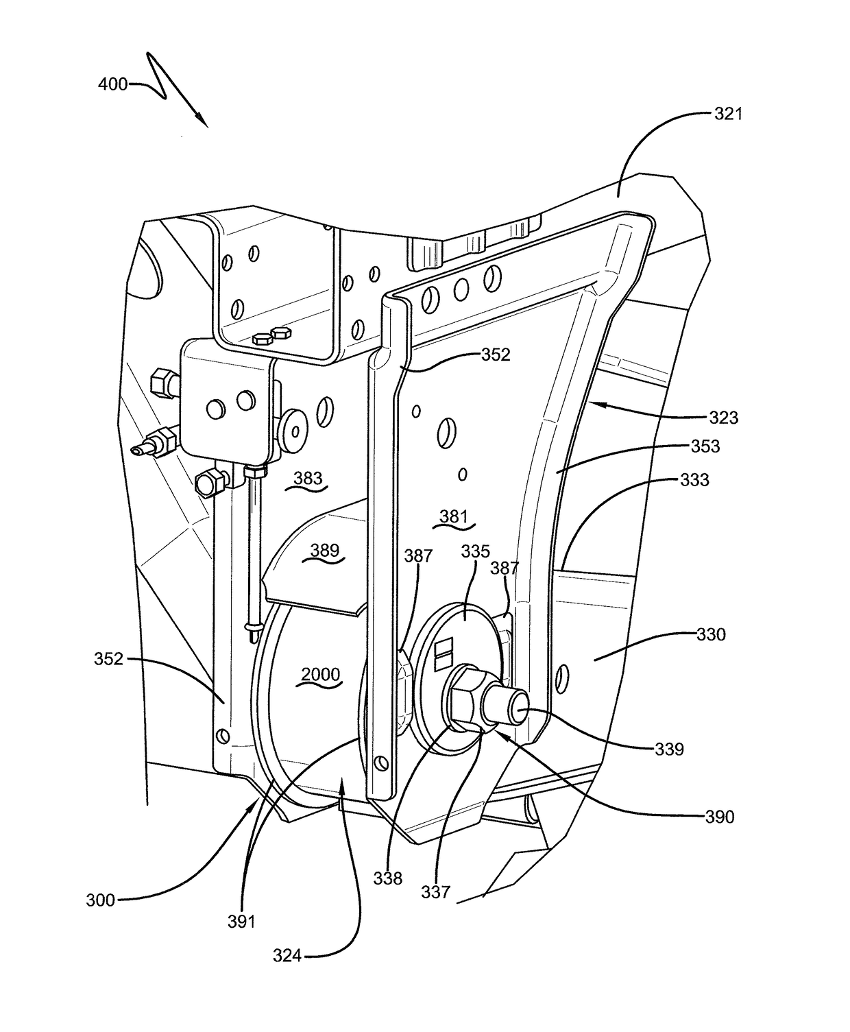
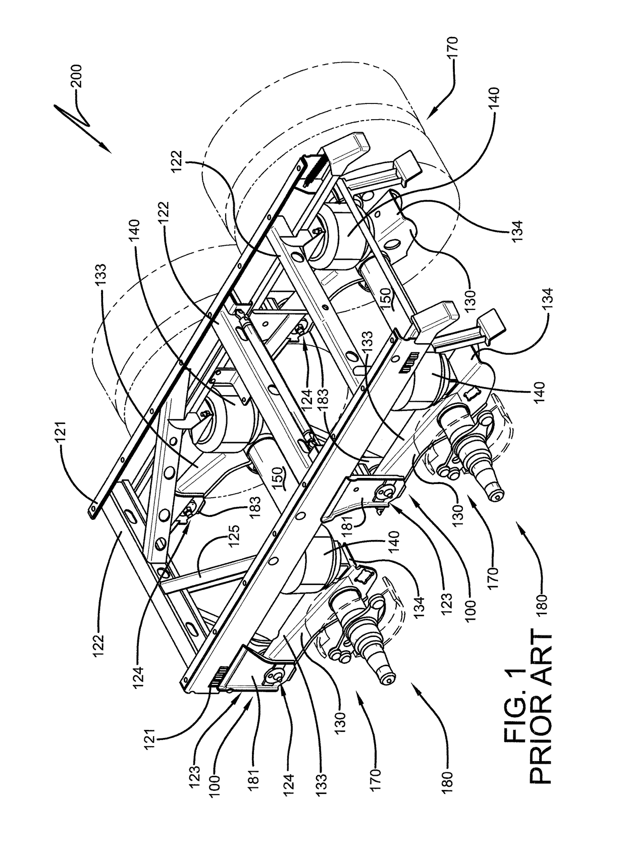
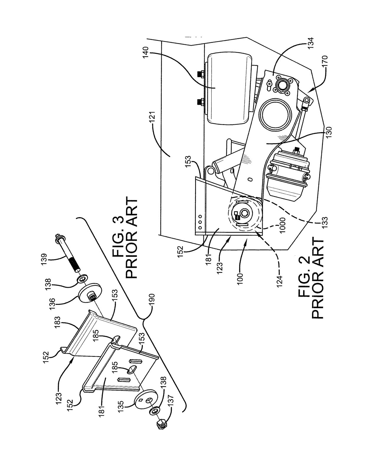
[0029]In order to better understand the structure, assembly and operation of the pivotal connection for a suspension assembly of a heavy-duty vehicle axle / suspension system, the structure, assembly and operation of a prior art pivotal connection will be described below. A prior art pivotal connection 100 is shown in FIG. 1. Typically, pivotal connection 100 is incorporated into a heavy-duty vehicle frame 200. Pivotal connection 100 is provided between a hanger 123 and a trailing arm beam 130 through a bushing assembly 124 and fastening means or a fastener group 190 (FIG. 3) including a bolt 139, a pair of washers 138, a nut 137, and optionally a concentric member 136 and an eccentric member 135. Because an axle / suspension system generally includes an identical pair of suspension assemblies 170 which are connected to heavy-duty vehicle frame 200 by a respective one of a pair of pivotal connections 100, for sake of clarity only one of the suspension assemblies and respective pivotal c...


PUM


Abstract

A suspension assembly of an axle / suspension system for a heavy-duty vehicle is mounted on the heavy-duty vehicle frame or sub-frame via a beam of the suspension assembly which is pivotally connected to a hanger connected to the vehicle frame. The pivotal connection includes the hanger, the beam, a bushing assembly and a fastener group, and a textured feature formed in at least one of at least a portion of the hanger, at least a portion of the bushing assembly, or at least a portion of the fastening means so that the textured feature inhibits relative movement of the bushing assembly with respect to the hanger.

Description

CROSS-REFERENCE TO RELATED APPLICATION[0001]This application claims the benefit of U.S. Provisional Patent Application Ser. No. 62 / 265,616, filed Dec. 10, 2015.BACKGROUND OF THE INVENTION[0002]Field of the Invention[0003]The subject matter relates to a frame and an axle / suspension system for a heavy-duty vehicle. More particularly, the disclosed subject matter is directed to a pivotal connection between a frame hanger and a beam of the axle / suspension system.[0004]Background Art[0005]Heavy-duty vehicles that transport cargo, for example, tractor-trailers or semi-trailers, and straight trucks such as dump trucks, typically include a leading or trailing arm axle / suspension system that connects an axle of the heavy-duty vehicle to a frame or sub-frame of the heavy-duty vehicle. Although such axle / suspension systems are found in widely varying structural forms, in general their structure is similar in that each axle / suspension system typically includes a pair of suspension assemblies. I...

Claims


Application Information

Patent Timeline
Patent Type & Authority Applications(United States)
IPC IPC(8): B60G7/02B60G3/14
CPCB60G7/02B60G2206/601B60G2206/017B60G3/145B60G2200/31B60G2200/462B60G2204/143B60G2204/41B60G2204/4302B60G2204/4402B60G2206/8207B60G2300/026B62D17/00F16B2/005F16B39/28
Inventor ANDREASEN, JACOB D.RAMUS, JASON M.
Owner HENDRICKSON USA L L C
Why Eureka
Try Eureka