Railroad car coupling system

a technology for coupling systems and railroad cars, applied in the field of railroad cars, can solve the problems of increasing the damage to railcars, increasing the length of railcars, and often exceeding the design load set by the aar, and achieve the effect of preventing potential separation of couplers

Active Publication Date: 2017-06-15
MINER ENTERPRISES INC
View PDF0 Cites 13 Cited by
  • Summary
  • Abstract
  • Description
  • Claims
  • Application Information

AI Technical Summary

Benefits of technology

[0017]According to another feature of this invention disclosure, there is provided a railroad car coupling system extending longitudinally into a car center sill structure for releasably connecting adjacent railcar ends. The center sill structure defines a cavity, a longitudinal axis, along with longitudinally spaced pairs of front and rear stops. According to this aspect of the invention disclosure, the coupling system includes a yoke movably retained within the cavity defined by the center sill structure. The yoke has a longitudinal axis arranged in general alignment with the center sill longitudinal axis and includes top and bottom walls which extend longitudinally and generally parallel to each other. The top and bottom and bottom walls of the yoke are connected to a rear wall so as to define a yoke pocket with an open end. The top wall of the yoke has two forward facing stops which are arranged in generally coplanar relationship relative to each other and extend in opposed lateral directions relative to the longitudinal axis of the yoke. The bottom wall of the yoke has two forward facing stops which are arranged in generally coplanar relationship relative to each other and extend in opposed lateral directions relative to the longitudinal axis of the yoke. The forward facing stops on the top and bottom walls of the yoke are arranged in generally coplanar relationship relative to each other. Preferably, the stops on the yoke prevent potential separation of the coupler from the center sill structure.

Problems solved by technology

Moreover, and because of their increased capacity, railcars are heavier than before.
These two factors and others have resulted in increased damages to the railcars when they collide and, frequently, to the lading carried within such railcars.
Whereas, such longitudinal loads frequently exceed the design loads set by the AAR.
As a result of the slack being progressively taken up, the speed difference between the railcars increases as the slack inherent with each coupling system at each end of the railcar in the train consist is taken up, with the resultant increase in buff and draft impacts on the coupling system.
Such large impact events are capable of damaging the lading in the railcars.
While bridging the distance between adjacent railcars, the length of such air hoses is limited unless two or more air hoses are coupled to each other whereby adding to the overall cost.
Of course, if the distance between the railcars exceeds the length of the air hose, the air hoses will separate from each other thereby affecting control over the braking function.

Method used


Image

  • Railroad car coupling system
  • Railroad car coupling system
  • Railroad car coupling system

Examples


Embodiment Construction

[0041]While this invention disclosure is susceptible of embodiment in multiple forms, there is shown in the drawings and will hereinafter be described preferred embodiments, with the understanding the present disclosure is to be considered as setting forth an exemplification of the disclosure which is not intended to limit the disclosure to the specific embodiments illustrated and described.

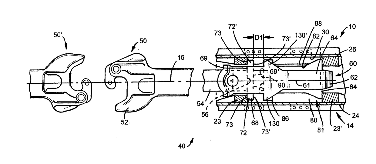
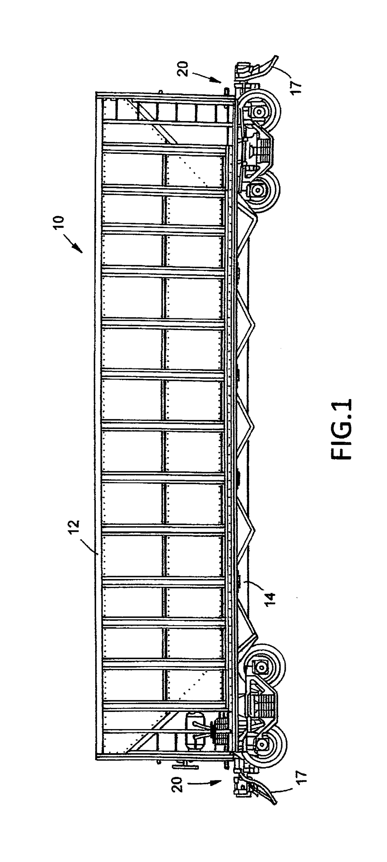
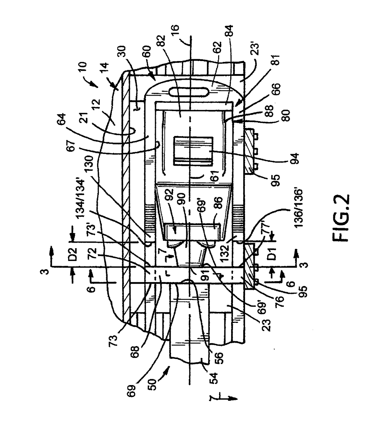
[0042]Referring now to the drawings, wherein like reference numerals indicate like parts throughout the several views, there is shown in FIG. 1 a railroad car, generally indicated by reference numeral 10. Although a railroad freight car is illustrated in the drawings for exemplary purposes, it will be appreciated the teachings and principals of this invention disclosure relate to a wide range of railcars including but not limited to railroad freight cars, tank cars, railroad hopper cars, and etc. Suffice it to say, railcar 10 has a railcar body 12, in whatever form, supported on a draft sill or c...


PUM


Abstract

A railroad car coupling system including a draft sill with front and rear stops, a coupler along with an energy management assembly for receiving and dissipating external forces experienced by the coupler. A yoke also forms part of the coupling system and is operably coupled to the coupler. The yoke includes top and bottom walls which each include two forward facing stops. A follower is mounted substantially between the top and bottom walls of the yoke for receiving forces experienced by the coupler. The follower is configured with two laterally spaced vertical extensions disposed toward opposed upper corners of the follower and two laterally spaced vertical extensions disposed toward opposed lower corners of the follower. Forward facing surfaces on the follower extensions arc arranged in generally coplanar relationship relative to each other. Rearward facing surfaces on the follower extensions are arranged in generally coplanar relationship with each other and operably engage with the forward facing stops on the yoke to enhance the distribution of forces when the follower engages the front stops on the center sill when the coupling system is in a full draft condition.

Description

RELATED APPLICATION[0001]This patent application is a Continuation-In-Part patent application of copending and coassigned patent application Ser. No. 14 / 540,209, filed, Nov. 13, 2014; the entirety of which is incorporated herein by reference.FIELD OF THE INVENTION DISCLOSURE[0002]The present invention disclosure generally relates to railroad cars and, more specifically, to a railroad car coupling system for releasably connecting adjacent railcar ends to each other.BACKGROUND[0003]During the process of assembling or “making-up” a train consist, railcars are run into and collide with each other to couple them together. Since time is money, the speed at which the railcars are coupled has significantly increased. Moreover, and because of their increased capacity, railcars are heavier than before. These two factors and others have resulted in increased damages to the railcars when they collide and, frequently, to the lading carried within such railcars.[0004]As railroad car designer / buil...

Claims


Application Information

Patent Timeline
Patent Type & Authority Applications(United States)
IPC IPC(8): B61G9/04B61G11/18B61G9/24
CPCB61G9/04B61G3/04B61G11/18B61G9/24
Inventor SCHOEDL, ERICH A.JAMES, KENNETH A.KRIES, ANDY R.
Owner MINER ENTERPRISES INC
Why Eureka
Try Eureka