Unlock instant, AI-driven research and patent intelligence for your innovation.
Hydraulic drive system
Active Publication Date: 2017-06-15
KAWASAKI HEAVY IND LTD
View PDF9 Cites 9 Cited by
Summary
Abstract
Description
Claims
Application Information
AI Technical Summary
This helps you quickly interpret patents by identifying the three key elements:
Problems solved by technology
Method used
Benefits of technology
Benefits of technology
The present invention provides a hydraulic drive system capable of detecting failures in solenoid proportional valves with an inexpensive configuration, and when detecting such a failure, bringing the corresponding control valve back to the neutral position. The failure of a solenoid proportional valve can be detected by simply installing a movement detection line or a discharge-pressure-measuring pressure sensor on the circulation line. This invention helps to reduce the cost of detecting and repairing failures in hydraulic drive systems.
Problems solved by technology
Thus, there is a problem of high cost.
Method used
Image
Click on the blue label to locate the original text in one second.
Reading with bidirectional positioning of images and text.
Examples
embodiment 1
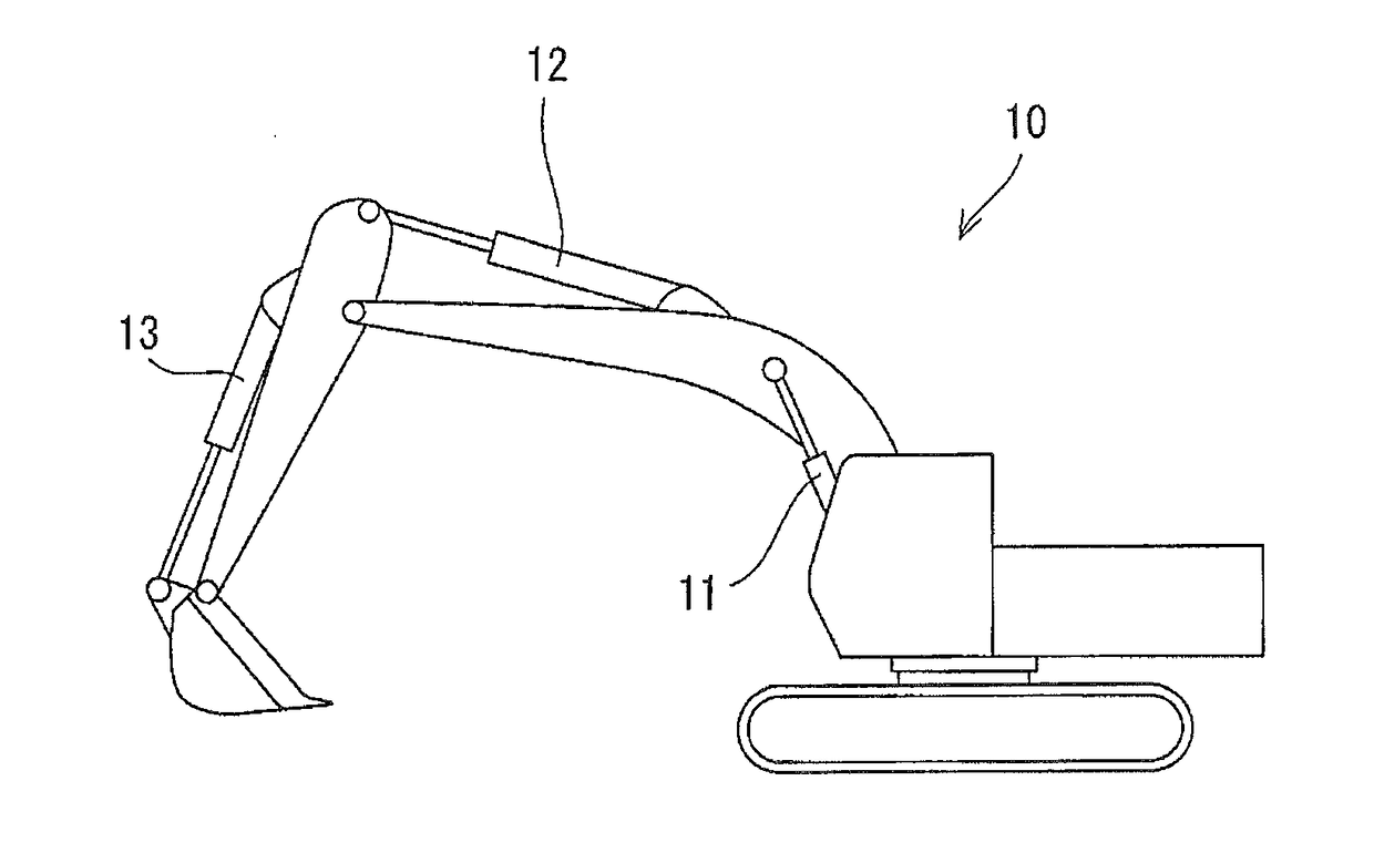
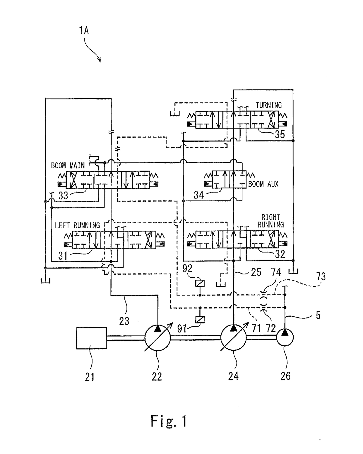
[0030]FIG. 1 and FIG. 2 show a hydraulic drive system 1A according to Embodiment 1 of the present invention. In the present embodiment, the hydraulic drive system 1A is a hydraulic drive system of a self-propelled hydraulic excavator 10 shown in FIG. 3.
[0031]Specifically, the hydraulic drive system 1A includes, as hydraulic actuators, a boom cylinder 11, an arm cylinder 12, and a bucket cylinder 13, which are shown in FIG. 3, and a turning motor, a left running motor, and a right running motor, which are not shown. A first main pump 22 and a second main pump 24 shown in FIG. 1 supply hydraulic oil to these actuators. The first main pump 22 and the second main pump 24 are driven by an engine 21. The engine 21 also drives an auxiliary pump 26.
[0032]As shown in FIG. 1, a first circulation line 23 extends from the first main pump 22 to a tank. A left running control valve 31 and a boom main control valve 33 are disposed on the first circulation line 23. Although not illustrated, an arm ...
embodiment 2
[0052]Next, a hydraulic drive system 1B according to Embodiment 2 of the present invention is described with reference to FIG. 4. It should be noted that, in the present embodiment and Embodiments 3 to 5 described below, the same components as those described in Embodiment 1 are denoted by the same reference signs as those used in Embodiment 1, and repeating the same descriptions is avoided below.
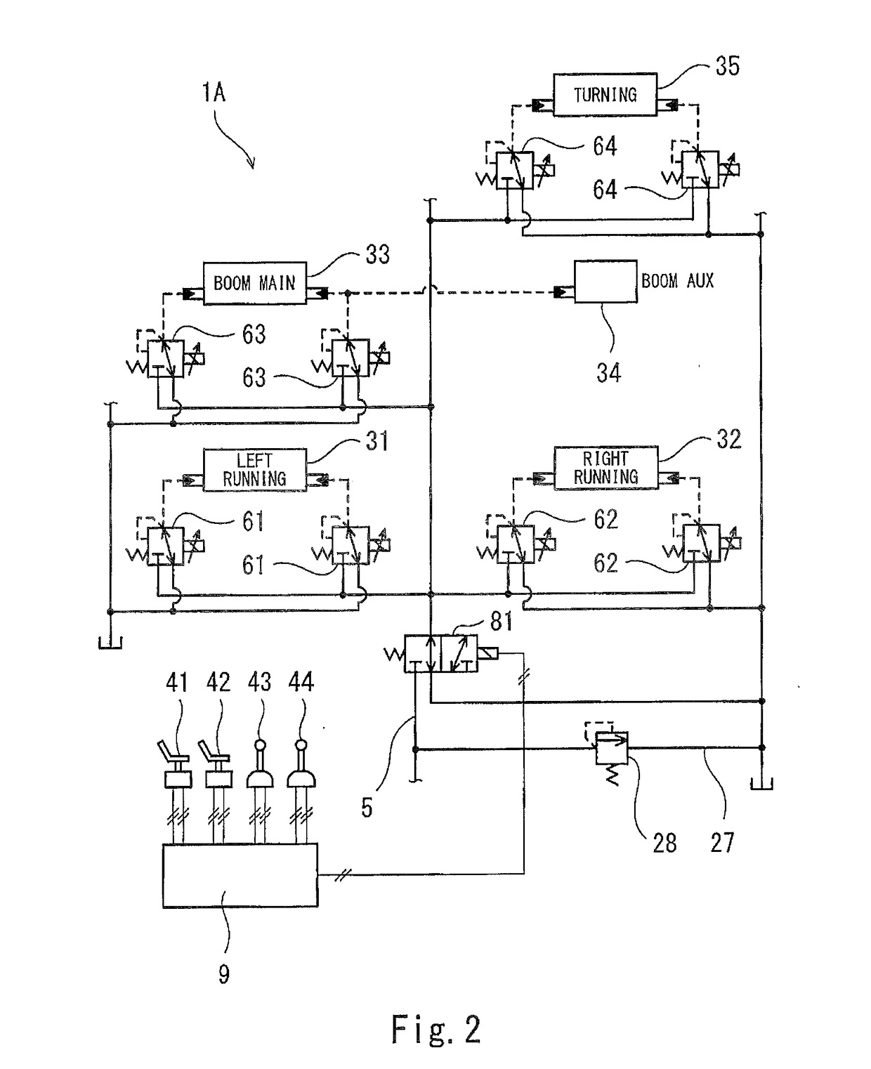
[0053]In the present embodiment, the main circuit of the hydraulic drive system 1B is the same as the main circuit shown in FIG. 1, and only the operation circuit thereof is different from that described in Embodiment 1. Specifically, the primary pressure line 5 includes: a running operation passage 51, which leads the hydraulic oil from the auxiliary pump 26 to the first running operation solenoid proportional valves 61 and the second running operation solenoid proportional valves 62; and a non-running operation passage 52, which leads the hydraulic oil from the auxiliary pump 26 to the fo...
embodiment 3
[0059]Next, with reference to FIG. 5, a hydraulic drive system 1C according to Embodiment 3 of the present invention is described.
[0060]In the present embodiment, the operation circuit of the hydraulic drive system 1C is the same as the operation circuit shown in FIG. 2, and only the main circuit thereof is different from that described in Embodiment 1. Specifically, the present embodiment does not include the first movement detection line 71 and the second movement detection line 73. Instead, the first circulation line 23 is provided with a first pressure sensor (a discharge-pressure-measuring pressure sensor) 93, and the second circulation line 25 is provided with a second pressure sensor (a discharge-pressure-measuring pressure sensor) 94. The first pressure sensor 93 measures the discharge pressure of the first main pump 22, and the second pressure sensor 94 measures the discharge pressure of the second main pump 24.
[0061]While any of the operation devices is outputting an elect...
PUM
Abstract
A hydraulic drive system includes: control valves; solenoid proportional valves outputting pilot pressures to the control valves; a controller controlling each of the solenoid proportional valves; a primary pressure line leading hydraulic oil from an auxiliary pump to the solenoid proportional valves; a solenoid switching valve provided on the primary pressure line; a movement detection line blocked when any of movement detectiontarget control valves has moved; and a movement detectionpressure sensor provided on the movement detection line. The controller controls the solenoid switching valve while all of operation devices are outputting electrical signals indicating that their operating levers are in neutral, such that: the solenoid switching valve opens the primary pressure line if a measurement value of the pressure sensor is less than a threshold; and the solenoid switching valve blocks the primary pressure line if the measurement value of the pressure sensor is greater than the threshold.
Description
BACKGROUND OF THE INVENTION[0001]1. Field of the Invention[0002]The present invention relates to a hydraulic drive system installed in, for example, construction machines.[0003]2. Description of the Related Art[0004]In a hydraulic drive system applied to an industrial machine, construction machine, or the like, hydraulic oil is supplied from a main pump to a plurality of hydraulic actuators. Specifically, a circulation line extends from the main pump to a tank, and a plurality of control valves are disposed on the circulation line. Each control valve controls hydraulic oil supply to and hydraulic oil discharge from a corresponding one of the actuators.[0005]The control valves may be operated by pilot operation valves that output pilot pressures, or may be operated by operation devices that output electrical signals. In the latter case, generally speaking, each control valve receives pilot pressures outputted from a pair of solenoid proportional valves. For example, Japanese Laid-Ope...
Claims
Application Information
Patent Timeline
Application Date:The date an application was filed.
Publication Date:The date a patent or application was officially published.
First Publication Date:The earliest publication date of a patent with the same application number.
Issue Date:Publication date of the patent grant document.
PCT Entry Date:The Entry date of PCT National Phase.
Estimated Expiry Date:The statutory expiry date of a patent right according to the Patent Law, and it is the longest term of protection that the patent right can achieve without the termination of the patent right due to other reasons(Term extension factor has been taken into account ).
Invalid Date:Actual expiry date is based on effective date or publication date of legal transaction data of invalid patent.

