
Distributed direct drive arrangement for driving cells

Active Publication Date: 2017-06-15
KYMETA
View PDF7 Cites 23 Cited by
  • Summary
  • Abstract
  • Description
  • Claims
  • Application Information

AI Technical Summary

Benefits of technology

The patent describes a method and device for directly driving cells, such as liquid crystal or MEMS cells, using an antenna array with multiple cells. The device includes circuitry to provide a voltage to each cell and a memory to store data values to determine if the cell is on or off. The technical effect is a more efficient and precise mechanism for driving cells in a direct manner.

Problems solved by technology

Some implementations of an antenna array utilizing thin film transistor (TFT) manufacturing processes have limitations in the refresh rate of the array due to use of high-birefringence liquid crystal (LC) with concomitant low voltage holding ratio.
That is, the low voltage holding ratio occurs at the same time as the limitations in the refresh rate of the array due to the high-birefringence LC.
A large storage capacitor in combination with the poor channel resistance, Rds, of typical amorphous silicon TFTs results in large charging time constants, which prevents refresh rates that achieve antenna tracking rate requirements.
This method becomes a challenge as the time to charge the LC cell and storage capacitor increases.
However, a large storage capacitance means a large charging time, and thus lower refresh rates.

Method used


Image

  • Distributed direct drive arrangement for driving cells
  • Distributed direct drive arrangement for driving cells
  • Distributed direct drive arrangement for driving cells

Examples


examples of antenna embodiments

[0076]The techniques described above may be used with flat panel antennas. Embodiments of such flat panel antennas are disclosed. The flat panel antennas include one or more arrays of antenna elements on an antenna aperture. In one embodiment, the antenna elements comprise liquid crystal cells. In one embodiment, the flat panel antenna is a cylindrically fed antenna that includes matrix drive circuitry to uniquely address and drive each of the antenna elements that are not placed in rows and columns. In one embodiment, the elements are placed in rings.

[0077]In one embodiment, the antenna aperture having the one or more arrays of antenna elements is comprised of multiple segments coupled together. When coupled together, the combination of the segments form closed concentric rings of antenna elements. In one embodiment, the concentric rings are concentric with respect to the antenna feed.

Overview of an Examples of Antenna Systems

[0078]In one embodiment, the flat panel antenna is part ...

an example system embodiment

[0134]In one embodiment, the combined antenna apertures are used in a television system that operates in conjunction with a set top box. For example, in the case of a dual reception antenna, satellite signals received by the antenna are provided to a set top box (e.g., a DirecTV receiver) of a television system. More specifically, the combined antenna operation is able to simultaneously receive RF signals at two different frequencies and / or polarizations. That is, one sub-array of elements is controlled to receive RF signals at one frequency and / or polarization, while another sub-array is controlled to receive signals at another, different frequency and / or polarization. These differences in frequency or polarization represent different channels being received by the television system. Similarly, the two antenna arrays can be controlled for two different beam positions to receive channels from two different locations (e.g., two different satellites) to simultaneously receive multiple...


PUM


Abstract

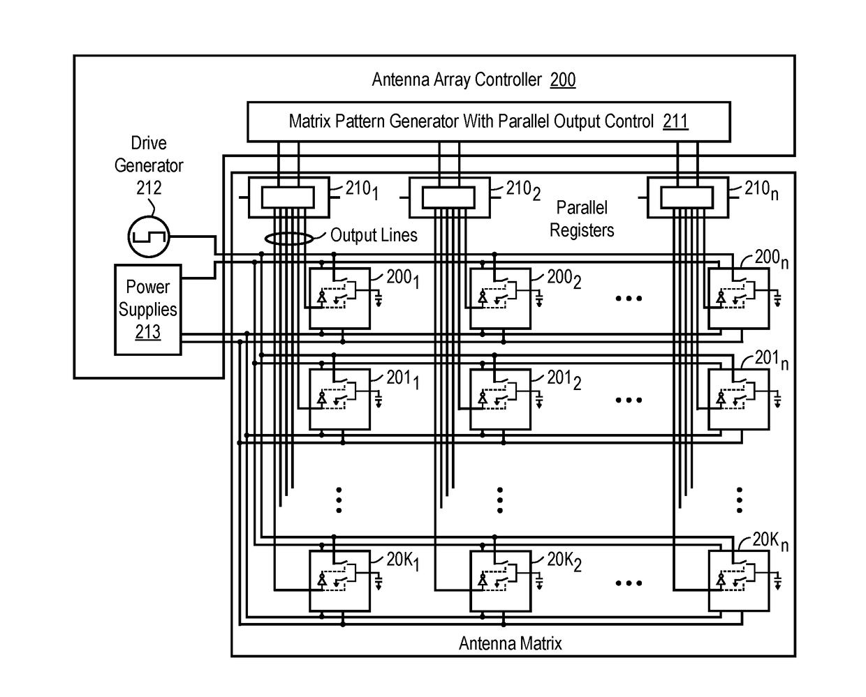
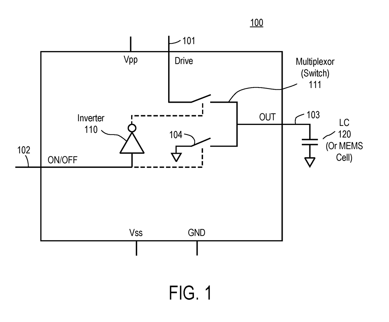
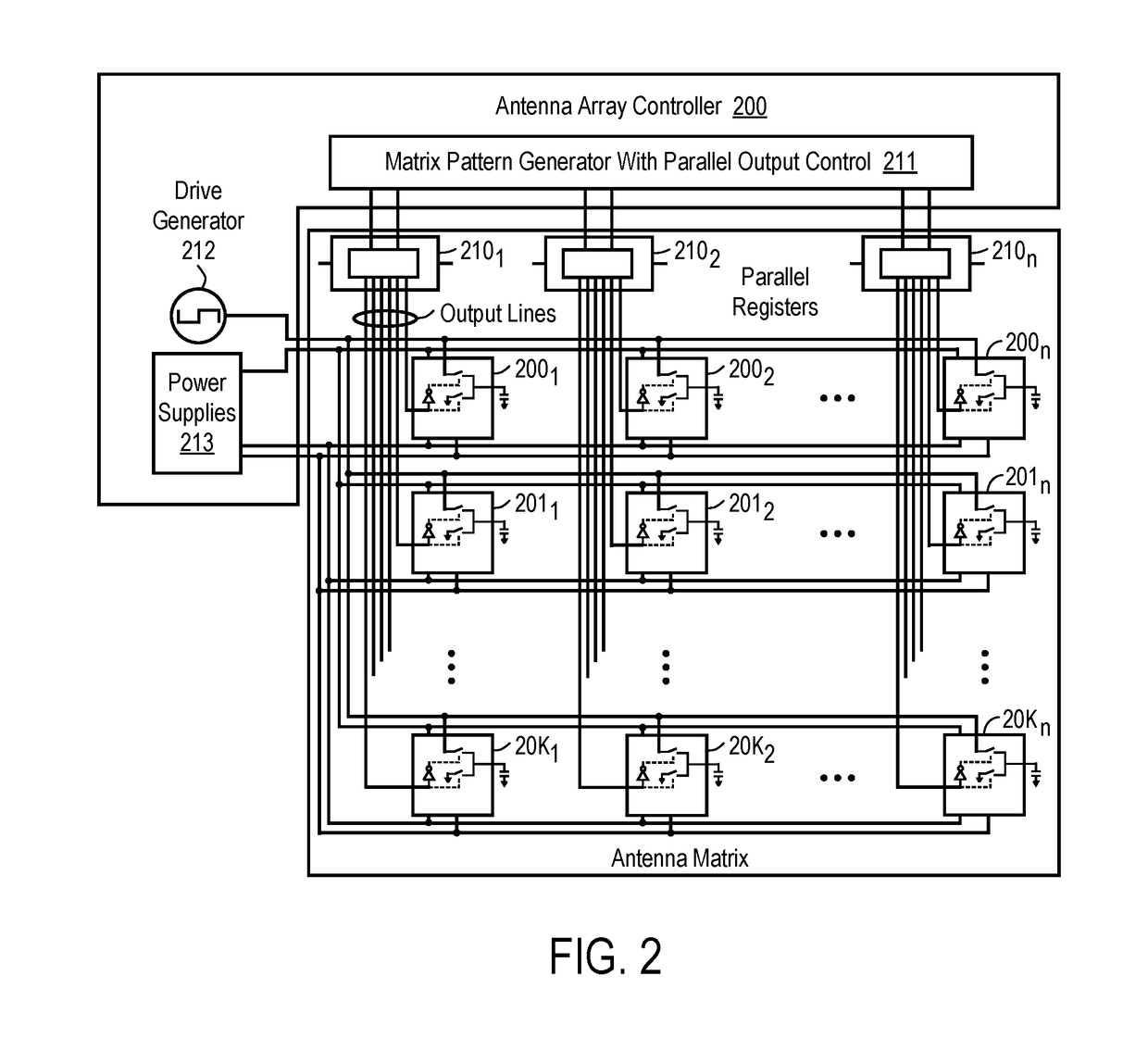
A method and apparatus is disclosed herein for a direct drive mechanism for driving cells (e.g., liquid crystal (LC) cells, RF MEMS cells, etc.). In one embodiment, the antenna comprises an antenna element array having a plurality of antenna elements with each antenna element having one or more cells (e.g., liquid crystal (LC) cell, RF MEMS cell, etc.); drive circuitry coupled to cells in the antenna element array to provide a voltage to each of the cells; and memory to store a data value for each cell to determine whether the cell is on or off.

Description

PRIORITY[0001]The present patent application claims priority to and incorporates by reference the corresponding provisional patent application Ser. No. 62 / 267,719, titled, “a-Si DISTRIBUTED DIRECT DRIVE: A MEMORY CELL WITH ANALOG SWITCH IN A MATRIX CONFIGURATION,” filed on Dec. 15, 2015.FIELD OF THE INVENTION[0002]Embodiments of the present invention relate to the field of antennas; more particularly, embodiments of the present invention relate to antennas having a direct drive to drive multiple cells in an antenna element array.BACKGROUND OF THE INVENTION[0003]Some implementations of an antenna array utilizing thin film transistor (TFT) manufacturing processes have limitations in the refresh rate of the array due to use of high-birefringence liquid crystal (LC) with concomitant low voltage holding ratio. That is, the low voltage holding ratio occurs at the same time as the limitations in the refresh rate of the array due to the high-birefringence LC. To compensate for this, a large...

Claims


Application Information

Patent Timeline
IPC IPC(8): H01Q21/06H01Q9/04
CPCH01Q9/0442H01Q21/064H01Q1/38H01Q21/0012H01Q21/0031
Inventor SEVERSON, MICHAELKUNDTZ, NATHAN
Owner KYMETA
Learn More