
Smart utility tower

Inactive Publication Date: 2017-06-22
TOTEM POWER INC
View PDF1 Cites 23 Cited by
  • Summary
  • Abstract
  • Description
  • Claims
  • Application Information

AI Technical Summary

Benefits of technology

The invention is a utility tower that can generate, store, and distribute power. It can be used for structures, electric vehicles, drones, and other portable electric devices. It also allows for prioritized power provisioning, grid balancing, cost optimizations, and environmental protections. The utility tower can monitor power, viability, and security of a utility tower. Additionally, it can provide power to multiple load types and can even include a canopy with a renewable energy source. Overall, the invention offers a versatile and efficient solution for generating and managing power in various applications.

Problems solved by technology

The power is typically generated at a large, centralized power plant, typically using power generation technology (e.g., coal, oil and / or nuclear) that can rely on a diminishing natural resource and / or can release unwanted emissions into the air and pollute the environment.
One difficulty with current power lines can be that they can be dependent upon the integrity of the physical structure of the line to provide power.
For example, during a storm power lines can break, causing one or more power line poles to fail to provide power.
Another difficulty with power line poles and / or power lines is that they can be aesthetically unpleasing.
Other difficulties with current power lines can include: (a) a lack of effective and / or real-time monitoring, for example, an inability to know the exact power lines that failed and / or on which power line pole the failure occurred, (b) a lack of effective and / or real-time security, for example, whether power is siphoned off and if so, at the physical location of the siphoning, (c) current power lines can be passive and have an inability to supply their own sources of energy for the power demanded, and / or (d) an inability for current poles to store energy for emergency needs.
In some cities, electronic vehicle charging stations have been deployed at select locations (e.g., by some grocery stores), however, these vehicle charging stations can be limited in number and / or are typically not a relied upon source for charging an electric vehicle.
For these renewable energy sources, energy captured in excess to what the grid can handle can be wasted and / or lost, due to, for example lack of a mechanism to store that excess energy.
One difficulty with current device charging is that if users forget to bring their chargers, charging on the go can be impossible.
Thus, many users run out of power on their portable electric devices before they have a chance to recharge.
Current unmanned vehicles can be limited by their battery life (e.g., approximately 30 minutes of flight time for drones), as most unmanned vehicles operate on a battery.
While it can be desirable to have a higher capacity battery in an unmanned vehicle to boost the battery life, a bigger battery can add undesirable weight to the unmanned vehicle, thus powering an unmanned vehicle with larger batteries can be difficult.

Method used


Image

  • Smart utility tower
  • Smart utility tower
  • Smart utility tower

Examples


Embodiment Construction

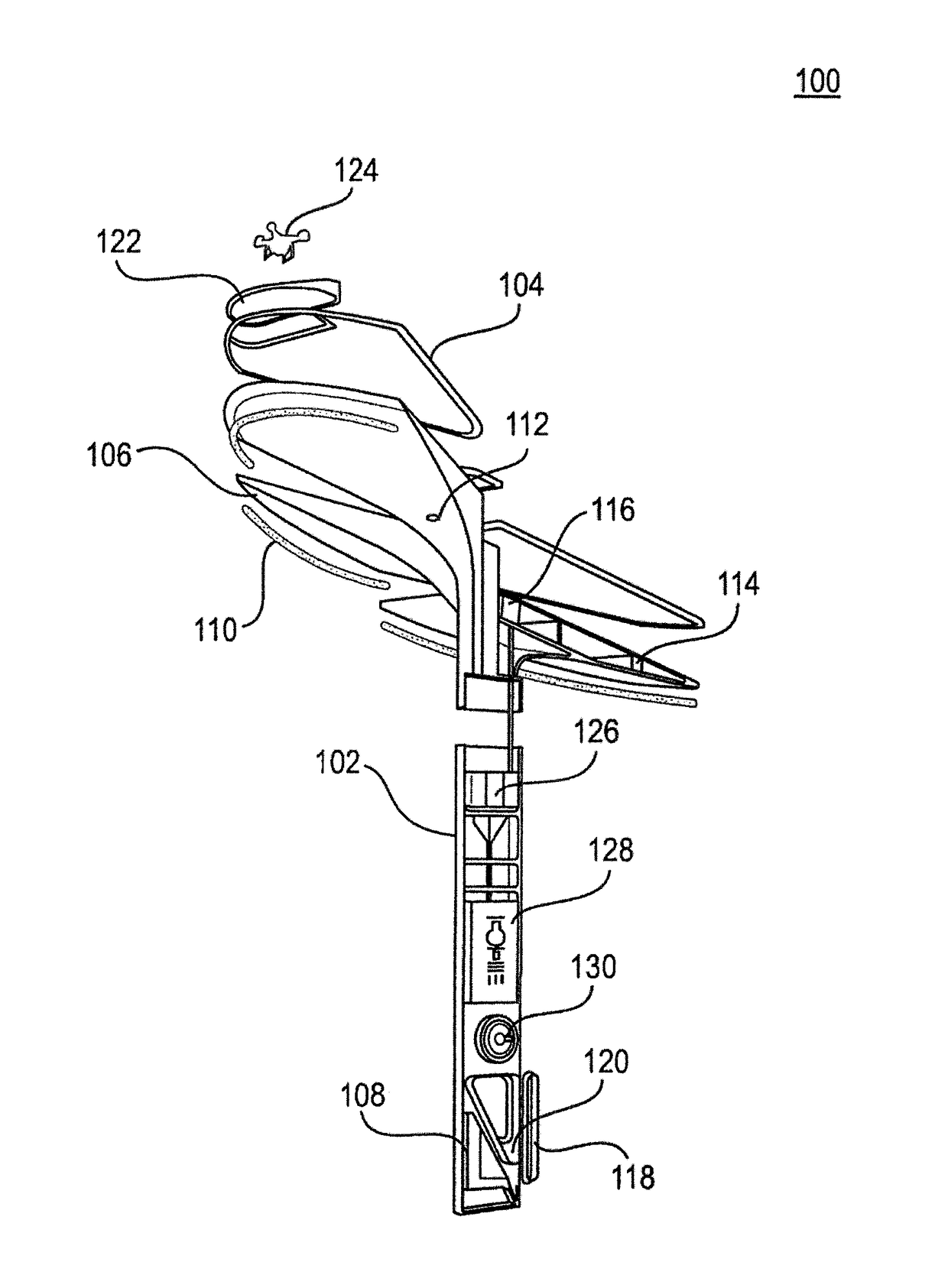
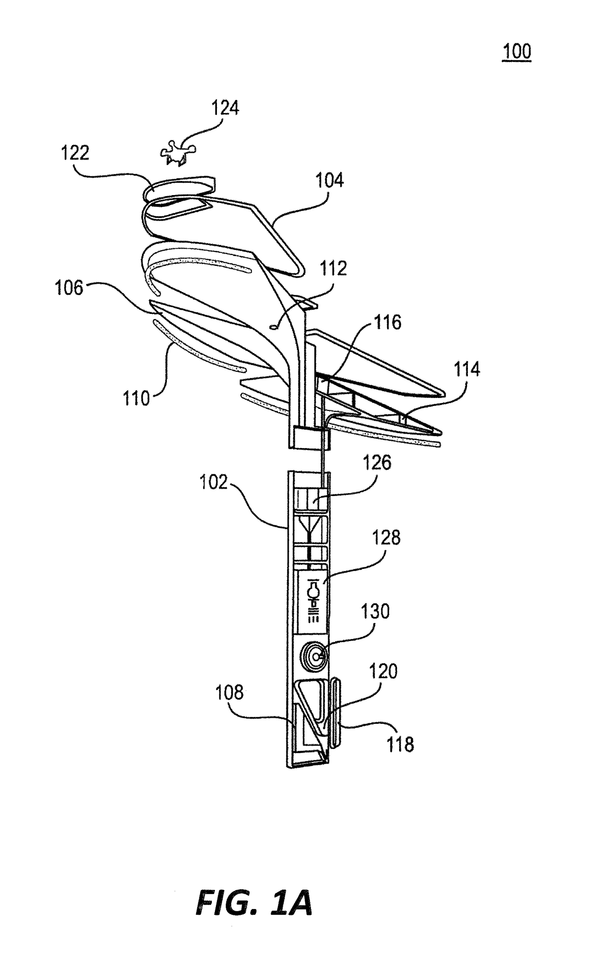
[0031]FIG. 1A is a cross-sectional diagram of a utility tower 100, according to an illustrative embodiment of the invention. The utility tower 100 includes a vertical structure, one or more lights 110a, 110b, and 110c, and a controller 108.

[0032]The vertical structure can include a utility pole 102 and a canopy structure, which can be a single form or include one or more canopy portions 106. In various embodiments, the number of canopy portions is 5. In some embodiments, the size of each canopy portions 106 is based on a size to accommodate one or more renewable energy sources (e.g., solar cells). In some embodiments, the canopy area ranges from 10 square feet to 300 square feet.

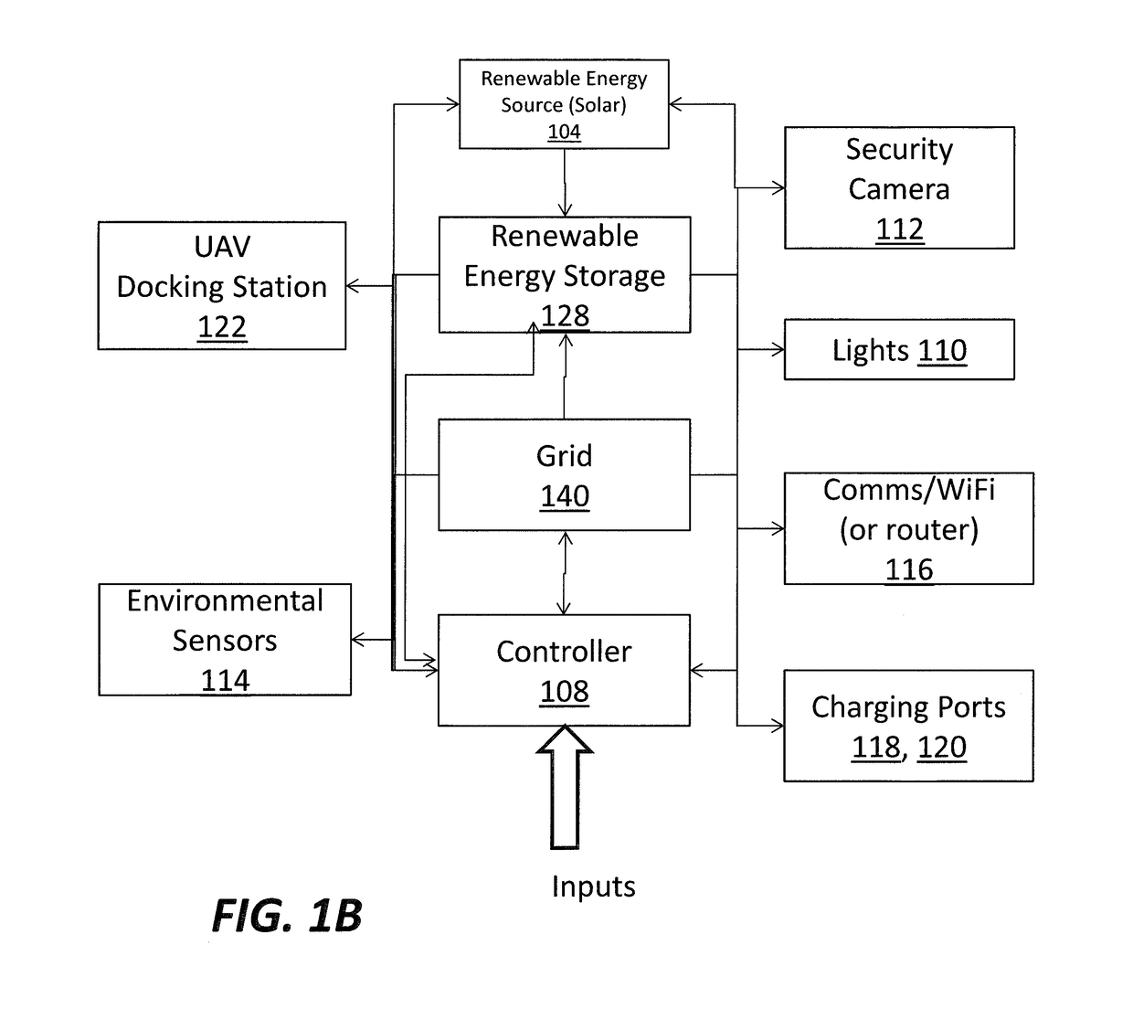
[0033]The utility pole 102 can include an energy storage 128, a converter 126, an electric vehicle charging port 118, a universal serial bus charging port 120, and / or the controller 108. In some embodiments, the utility tower 100 includes an inductive charger (not shown). In some embodiments, the utility pol...


PUM


Abstract

Systems and methods for energy generation, management and distribution via a utility tower are provided. The utility tower can include a vertical structure, at least one energy storage, at least one communication network to communicate power requirements, power quality, power available or any combination thereof, at least one power source coupled to the at least one energy storage, at least one controller to calculate at least one power distribution criterion and to control the energy transfer from the at least one energy storage to one or more loads based on the at least one power distribution criterion.

Description

CROSS REFERENCE TO RELATED APPLICATIONS[0001]This application claims benefit of and priority to U.S. provisional application No. 62 / 269,623, filed on Dec. 18, 2015, all of which are incorporated herein by reference in their entirety.FIELD OF THE INVENTION[0002]The invention relates generally to distributed power generation and energy distribution systems. More particularly, the invention relates to utility poles that can generate / provide clean and grid power to a variety of loads.BACKGROUND OF THE INVENTION[0003]Currently, power generation and / or distribution systems can provide power to participating parties (e.g., houses and / or buildings). The power is typically generated at a large, centralized power plant, typically using power generation technology (e.g., coal, oil and / or nuclear) that can rely on a diminishing natural resource and / or can release unwanted emissions into the air and pollute the environment.[0004]The associated networks typically provide power via a grid of inter...

Claims


Application Information

Patent Timeline
IPC IPC(8): B60L11/18H02J7/00H02J7/02H02J3/38
CPCB60L11/1816H02J3/383B60L2200/10H02J7/025H02J2007/0062H02J7/0052H02G3/0493H02J7/35B60L2240/80Y02T90/16Y04S10/126B60L53/31B60L53/63B60L53/305B60L53/51B60L53/52B60L53/53B60L53/57H02J2300/24H02J3/381Y02E10/56Y02E60/00Y02T10/7072Y02T90/12Y02T10/70H02J3/388Y02T90/14H02J7/00
Inventor LAKAMP, BRIAN DAVIDMARANO, ROBERT FRANK
Owner TOTEM POWER INC
Features
  • Generate Ideas
  • Intellectual Property
  • Life Sciences
  • Materials
  • Tech Scout
  • Unparalleled Data Quality
  • Higher Quality Content
  • 60% Fewer Hallucinations
Learn More