Thermostat stability enhancement via wavy valve plate

Inactive Publication Date: 2017-06-22
GM GLOBAL TECH OPERATIONS LLC
View PDF6 Cites 8 Cited by
  • Summary
  • Abstract
  • Description
  • Claims
  • Application Information

AI Technical Summary

Benefits of technology

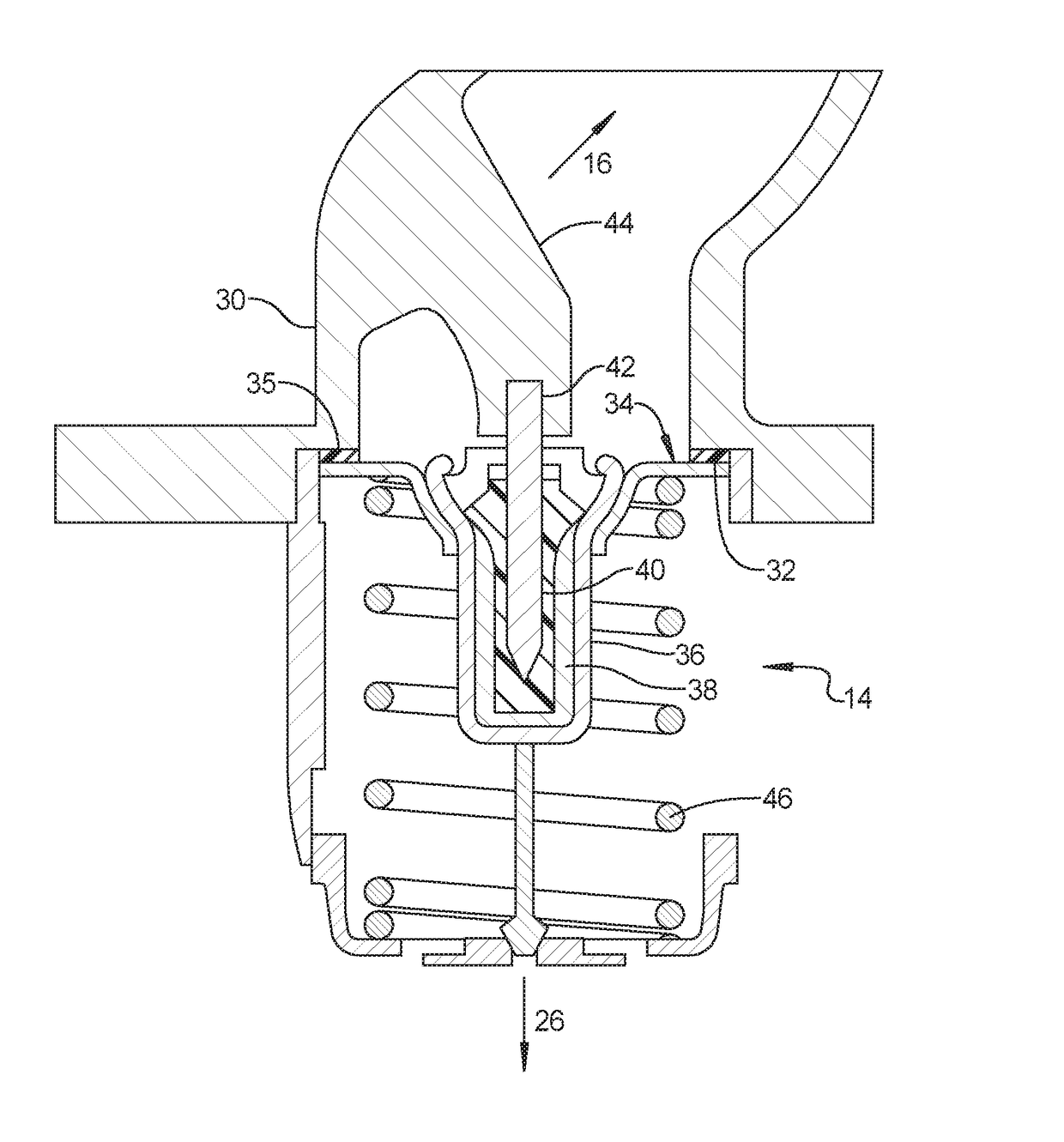
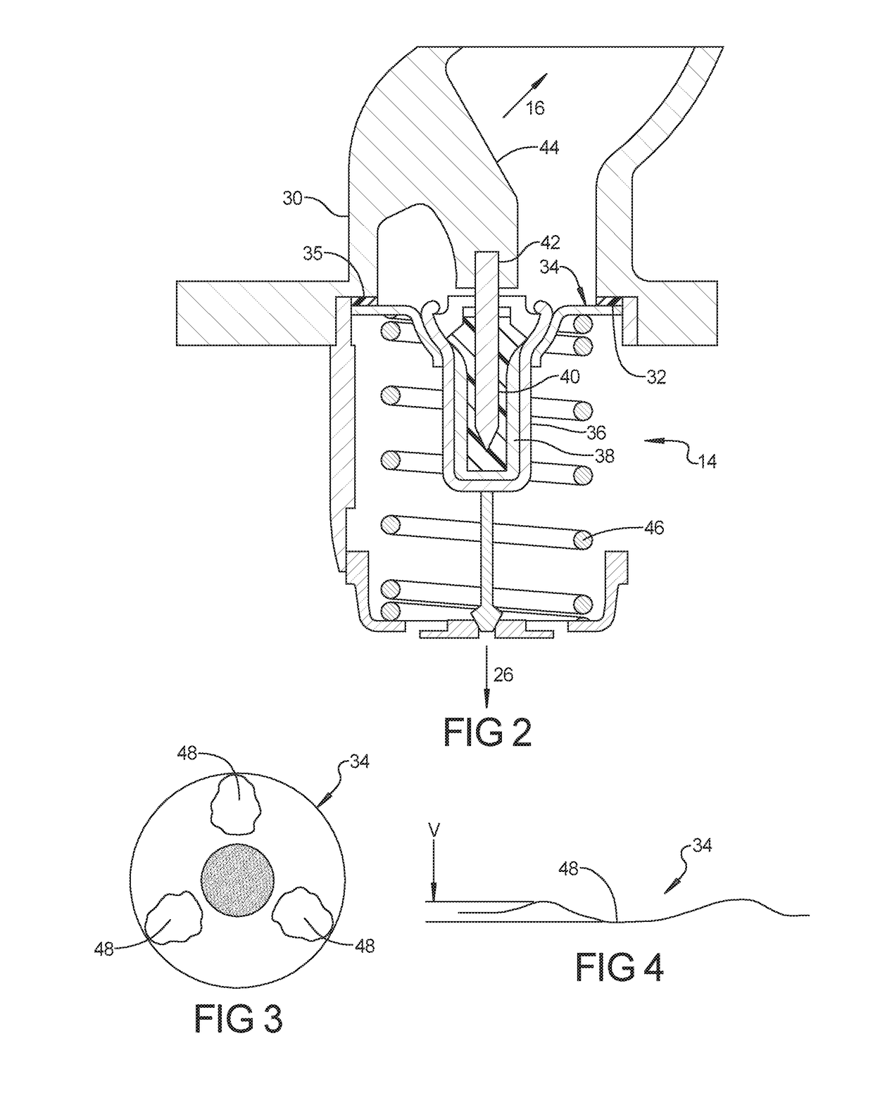
[0021]As compared to conventional thermostat valve plates that have a planar engagement surface, it has been discovered that the wavy valve plate configuration creates a situation where the thermostat 24 can regulate small amounts of flow during initial opening of the valve plate 34, resulting in an improved flow control as compared to a conventional flat plate design. The fine flow control during initial opening of the valve plate allows the thermostat 24 to be placed further away from the radiator 20 and provides a situation where the thermostat 24 can adjust the f

Problems solved by technology

Engine outlet side thermostats have historically been problematic with regards to control at low load conditions.
The result is that the radiator can be continuously exposed to thermal cycles to the po

Method used


Image

  • Thermostat stability enhancement via wavy valve plate
  • Thermostat stability enhancement via wavy valve plate
  • Thermostat stability enhancement via wavy valve plate

Examples


Embodiment Construction

[0012]Example embodiments will now be described more fully with reference to the accompanying drawings.

[0013]Example embodiments are provided so that this disclosure will be thorough, and will fully convey the scope to those who are skilled in the art. Numerous specific details are set forth such as examples of specific components, devices, and methods, to provide a thorough understanding of embodiments of the present disclosure. It will be apparent to those skilled in the art that specific details need not be employed, that example embodiments may be embodied in many different forms and that neither should be construed to limit the scope of the disclosure. In some example embodiments, well-known processes, well-known device structures, and well-known technologies are not described in detail.

[0014]The terminology used herein is for the purpose of describing particular example embodiments only and is not intended to be limiting. As used herein, the singular forms “a,”“an,” and “the” ...


PUM


Abstract

A thermostat for use in the coolant passage of an internal combustion engine includes a valve seat and a valve plate with an elastomeric seal engaged with the valve seat in a closed condition and movable away from the valve seat in an open condition. The valve plate has a wavy surface disposed below the elastomeric seal that engages the valve seat, wherein the wavy surface is nonplanar with surface variations of at least 300 microns. The wavy valve plate creates a situation where the thermostat operates with two effective modes, a low flow regime for low load conditions where the valve is only traveling between 0 and approximately 1 mm while the wavy plate allows a low coolant flow and a high flow regime (valve fully open) for high engine load situations that require maximum cooling.

Description

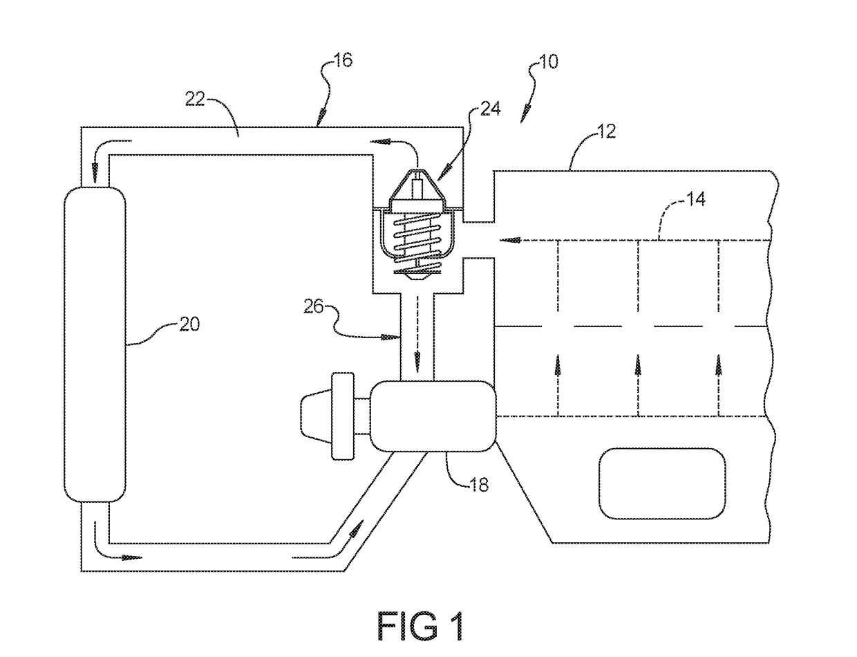
FIELD[0001]The present disclosure relates to thermostats for use with internal combustion engines, and more particularly to a thermostat having a wavy valve plate.BACKGROUND AND SUMMARY[0002]This section provides background information related to the present disclosure which is not necessarily prior art.[0003]Internal combustion engines typically employ a cooling system for maintaining the engine within a desired operating temperature range. The cooling system for many automotive vehicles employs a coolant fluid that is circulated through the cylinder block and cylinder head of the engine and through a radiator. A thermostat is used to regulate the flow of coolant to the radiator so as to maintain the coolant at a desired temperature. Engine outlet side thermostats have historically been problematic with regards to control at low load conditions. In modern systems this can cause the thermostat to continuously open and close at steady state highway speeds. The result is that the radi...

Claims


Application Information

Patent Timeline
IPC IPC(8): F01P7/16G05D23/185
CPCG05D23/1852F01P7/165G05D23/022
Inventor POISSON, MICHAELKARLSSON, ROLF B.SAINDON, WILLIAM C.GATOWSKI, JAN ANDRZEJDICKTY, DENNIS S.
Owner GM GLOBAL TECH OPERATIONS LLC
Why Eureka
Try Eureka