Snow quality measuring apparatus and snow quality measuring method

a technology of measuring apparatus and snow quality, applied in instruments, meteorology, etc., can solve the problems of inability to detect snow quality, inability to use unmanned automatic measurement, and difficulty in identifying changes in snow quality in the depth direction

Active Publication Date: 2017-06-22
TAIYO YUDEN KK
View PDF2 Cites 1 Cited by
  • Summary
  • Abstract
  • Description
  • Claims
  • Application Information

AI Technical Summary

Benefits of technology

[0019]In another aspect, the present disclosure provides a method of measuring snow quality, including: emitting radio waves toward a plurality of reflectors respectively installed at a plurality of prescribed heights from the ground; receiving reflected radio waves of the radio waves from two or more of the plurality of reflectors that are buried in snow on the ground; and measuring snow quality for the snow on the ground at multiple heights based on the received respective reflected waves from the two or more of the plurality of reflectors.
[0020]As described above, the present invention makes it possible to perform unmanned measurement of snow quality for each layer of snow on the ground in the depth direction. It is to be understood that both the foregoing general description and the following detailed description are exemplary and explanatory, and are intended to provide further explanation of the invention as claimed.

Problems solved by technology

The technique described in Patent Document 1 inserts a probe into a layer of snow to identify the snow quality within the snow on the ground, but requires someone to go to the measurement location and perform manual work, and is thus incapable of unmanned automatic measurement.
Furthermore, the technique described in Patent Document 2 uses ultrasonic waves to measure snow depth, but does not allow one to know the state inside the snow on the ground, and thus cannot detect snow quality.
Moreover, the technique described in Patent Document 3, in order to identify snow quality, measures the permittivity of snow on the ground by receiving reflected waves of radio waves emitted towards a reflector disposed at the base of the snow (on the ground), but this can only identify snow quality as an average of total snow and has difficulty in identifying changes in snow quality in the depth direction.

Method used


Image

  • Snow quality measuring apparatus and snow quality measuring method
  • Snow quality measuring apparatus and snow quality measuring method
  • Snow quality measuring apparatus and snow quality measuring method

Examples


embodiment 1

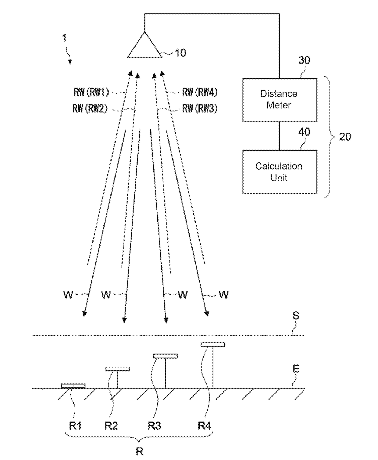
[0030]FIG. 1 is a schematic configuration diagram of a snow quality measuring apparatus according to Embodiment 1 of the present invention.

[0031](Snow Quality Measuring Apparatus)

[0032]A snow quality measuring apparatus 1 of the present embodiment is typically installed in mountainous areas, plains, or other locations that receive a lot of snow, and can perform unmanned measurement of depth, quality, etc. of the snow that has accumulated on the ground.

[0033]The snow quality measuring apparatus 1 includes a plurality of reflectors R1, R2, . . . (hereinafter collectively referred to as reflectors R unless being individually explained), an antenna 10 (transceiver), and a measuring device 20.

[0034]The plurality of reflectors R are respectively arranged at a plurality of prescribed heights above the ground E. FIG. 1 shows four reflectors R1 to R4 that have been installed in locations with mutually differing heights above the ground E. The first to fourth reflectors R1 to R4 are arranged ...

embodiment 2

[0069]FIG. 7 is a schematic configuration diagram of a snow quality measuring apparatus according to Embodiment 2 of the present invention. The configurations differing from Embodiment 1 will mainly be described below, and the same reference characters will be given to the components that are the same as Embodiment 1 described above; thus, repetitive explanations will be omitted or simplified.

[0070]A snow quality measuring apparatus 2 of the present embodiment is similar to Embodiment 1 in having the antenna 10, plurality of reflectors R (R1 to R4), and measuring device 20, but differs from Embodiment 1 in the relative positional relationship between the antenna 10 and the plurality of reflectors R.

[0071]In other words, in the snow quality measuring apparatus 2 of the present embodiment, the antenna 10 is not arranged directly over the respective reflectors R1 to R4, and the radio waves W for measurement are emitted to the respective reflectors R1 to R4 in a direction that is slante...

embodiment 3

[0074]FIG. 8 is a schematic configuration diagram of a snow quality measuring apparatus according to Embodiment 3 of the present invention. The configurations differing from Embodiment 1 will mainly be described below, and the same reference characters will be given to the components that are the same as Embodiment 1 described above; thus, repetitive explanations will be omitted or simplified.

[0075]A snow quality measuring apparatus 2 of the present embodiment is similar to Embodiment 1 in having the antenna 10, plurality of reflectors R (R1 to R4), and measuring device (not shown), but differs from Embodiment 1 in the relative positional relationship between the antenna 10 and the plurality of reflectors R.

[0076]In other words, in the snow measuring apparatus 3 of the present embodiment, the antenna 10 is constituted by a plurality of transceivers 101 to 104 facing reflectors R1 to R4 that are arranged at a prescribed plurality of height positions. Namely, the transceivers 101 to 1...


PUM


Abstract

A snow quality measuring apparatus according to one aspect of the present invention includes a plurality of reflectors, at least one transmitter, at least one receiver, and a measuring device. The plurality of reflectors are respectively arranged at a plurality of prescribed heights above the ground. The transmitter emits radio waves towards the plurality of reflectors, and the receiver receives the reflected waves of the radio waves from the plurality of reflectors. The measuring device measures snow quality of snow on the ground at the prescribed plurality of heights based on the respective reflected waves to from the plurality of reflectors as received by the receiver.

Description

BACKGROUND OF THE INVENTION[0001]Technical Field[0002]The present invention relates to a snow quality measuring apparatus and a method of measuring snow quality of snow on the ground using millimeter radio waves, for example.[0003]Background Art[0004]One type of natural disaster is that which is caused by snow. Namely, avalanches, roof collapses, etc. cause tremendous damage, and the effect on transportation systems such as railways or roads in cities represents a serious issue on a societal scale. As a countermeasure, ordinary information regarding snow typically involves snowfall amount, temperature, and wind direction, with predictions or the like being derived from these by using surface melting predictions or snow quality change estimation models based on solar radiation amount, snow density, etc.; however, these predictions require a vast amount of data and numerical analysis for each locality and are unsuitable for use with avalanches or extensive areas, for example.[0005]Mea...

Claims


Application Information

Patent Timeline
Patent Type & Authority Applications(United States)
IPC IPC(8): G01S13/88H01Q15/14
CPCH01Q15/14G01S13/88G01S13/34G01S13/885H01Q19/17H01Q19/185G01W1/14
Inventor AOKI, YUTAKASUNAGAWA, RYUICHIMIKATA, JINMURATA, RYUJI
Owner TAIYO YUDEN KK
Why Eureka
Try Eureka